Hello everyone,
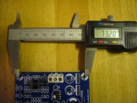
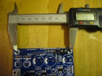
I've ordered one of these boards and wondered if anyone has the dimensions of the mounting holes to hand. I'd like to get on with bashing some holes in a case whilst I wait for delivery.
Thanks
Tony
I measure 72.7mm one side and 75.7mm on the long side (with the LED's).
I would wait for the board though, yours might be a different batch.
Bill
Sorry for the double post, I was replying at the same time as hotiron.... I had a few beers last night too, but it's eight in the morning here and I sobered up overnight.... bit of athough!
Bill
Like I said Bill "Where's the pizza" Hic!!!

Changes
I did not assemble it in stock form, so I am not able to give fair comments on your question. But I definitely prefer this MINI DAC compared to the stock PCM1793 DAC.
Piersma, did you listen to the DAC in its stock form before you got to your latest configuration/mod. If so, a subjective description of the changes you heard would be welcomed.
I did not assemble it in stock form, so I am not able to give fair comments on your question. But I definitely prefer this MINI DAC compared to the stock PCM1793 DAC.
Attachments
If you mounted an elco in C3, probably not but it could sound better with them.
You should try.
BTW why do you want to replace CS8416 analog PS?
many thanks for the help!
For analogue +3.3 part of CS8416 your shunt has been implemented, I removed completely U9, though didn't touch U6 as it was written here that there could be some voltage peaks during switching on/off the dac. Not sure if I've done it correctly...
For analogue +5v part salas shunt has been built.
C38 can be omitted but why would you omit also C14? IMHO it's needed to decouple the opamp, particularly with an external regulator.
Did you replaced also U10, right?
Exactly, I have replaced U9 & U10 by salas for two opamps (dac + preamp).
No, there's something wrong, maybe you burned the BD139.
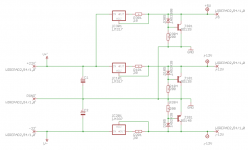
Can you post a schema of what you did?
My simple shunt has two sections: a current regulator (LM317 + current setting resistor) and zener+resistor+transistor as the real shunt.
that's weird as the dac is already assembled and has been working fine for 24h now.
the schema is your shunt (att) - LM+zener+BD139. Perhaps the zener was soldered vice versa?!
Attachments
many thanks for the help!
You're welcome
")
that's weird as the dac is already assembled and has been working fine for 24h now.
the schema is your shunt (att) - LM+zener+BD139. Perhaps the zener was soldered vice versa?!
No, you wouldn't read the zener voltage otherwise.
If you implemented correctly my schema (please double check) something goes wrong with your transistor.
The regulator also works with a burned transistor but the output voltage will be the zener one.
current setting resistor for Lm317 is 43 Ohm. Zener is BZX79/C8V2, R is 200 Ohm + BD139. hope this helps.
Perfectly fine, IMHO you have a bad/burned transistor or you have some component reversed/not correctly wired (probably the transistor).
THS4032CD run hot
Proper power-supply decoupling – Use a 6.8-µF tantalum capacitor in parallel with a 0.1-µF ceramic
capacitor on each supply terminal. It may be possible to share the tantalum among several amplifiers
depending on the application, but a 0.1-µF ceramic capacitor should always be used on the supply terminal
of every amplifier. In addition, the 0.1-µF capacitor should be placed as close as possible to the supply
terminal. As this distance increases, the inductance in the connecting trace makes the capacitor less
effective. The designer should strive for distances of less than 0.1 inch between the device power terminals
and the ceramic capacitors - taken from THS4032CD datasheet.
Maybe the problem is oscillation.
The other thing that is getting hot is the THS4032CD opamp I am using. I could only get it in a surface mount package and had to mount it on a DIP8 socket. Not sure what the best thing is to keep it cool.
Proper power-supply decoupling – Use a 6.8-µF tantalum capacitor in parallel with a 0.1-µF ceramic
capacitor on each supply terminal. It may be possible to share the tantalum among several amplifiers
depending on the application, but a 0.1-µF ceramic capacitor should always be used on the supply terminal
of every amplifier. In addition, the 0.1-µF capacitor should be placed as close as possible to the supply
terminal. As this distance increases, the inductance in the connecting trace makes the capacitor less
effective. The designer should strive for distances of less than 0.1 inch between the device power terminals
and the ceramic capacitors - taken from THS4032CD datasheet.
Maybe the problem is oscillation.
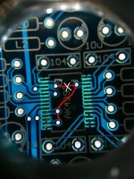
With a little mod on this board (ACKS pin to HI see pic), you can also set it in auto mode for master clock.
Hi Bismuth!
ACKS and TST1 pin in manual setting mode fixed to the analog GND. When auto setting mode enabled ACKS and DVS0 pin must be fixed to the DVSS or DVDD.
Here I do not see anywhere that you're separated ACKS from the GND pins?
Thanks
Hi Jazzbear!Hi Bismuth!
ACKS and TST1 pin in manual setting mode fixed to the analog GND. When auto setting mode enabled ACKS and DVS0 pin must be fixed to the DVSS or DVDD.
Here I do not see anywhere that you're separated ACKS from the GND pins?
Thanks
On the AK4396 chip, the ACKS pin is pin 28 (top right one on my last picture), you have to desolder this pin from the board, a little bit tricky operation due to component size (I used a very thin wire and a blade to bend the pin gently). Then you solder a bridge from this pin to DVDD ref in order to set ACKS to "HI", I used a simple wire for that purpose (the brown one on the pic).
I left TST1 (pin26) untouched.
DFSO (pin 9) is connected to pin 9 of the 74HC04 by a track (untouched).
PDN (pin 4) is connected to pin 12 of the 74HC04 by a track that I wired to VCC (pin 14 of 74HC04 emplacment) with a soldered jumper (see pic).
It works like this but I may have miss something ?
I2S setup
Hi Bismuth!
Page 8 in Datasheet:
TST1 This pin should be open(outputs Hi-Z in parallel mode)
TST2 This pin should be connected to DVSS(it should remain as is)
Everything else is done perfectly.
On bottom side:The line marked in red must be cut with a scalpel.
;Bismuth 3010167 said:Hi Jazzbear!
On the AK4396 chip, the ACKS pin is pin 28 (top right one on my last picture), you have to desolder this pin from the board, a little bit tricky operation due to component size (I used a very thin wire and a blade to bend the pin gently). Then you solder a bridge from this pin to DVDD ref in order to set ACKS to "HI", I used a simple wire for that purpose (the brown one on the pic).
I left TST1 (pin26) untouched.
DFSO (pin 9) is connected to pin 9 of the 74HC04 by a track (untouched).
PDN (pin 4) is connected to pin 12 of the 74HC04 by a track that I wired to VCC (pin 14 of 74HC04 emplacment) with a soldered jumper (see pic).
It works like this but I may have miss something ?
Hi Bismuth!
Page 8 in Datasheet:
TST1 This pin should be open(outputs Hi-Z in parallel mode)
TST2 This pin should be connected to DVSS(it should remain as is)
Everything else is done perfectly.
On bottom side:The line marked in red must be cut with a scalpel.
Attachments
Last edited:
Got My 96s Back
Hey, The new PCB (eBay along1986090 $18 w/ 3chips pre-soldered inc. shpng) and Dario's Upgrade BOM went together without a hitch - almost - and powered up properly on the first try. The sound is appearing balanced from both channels - but the "No Audio" LED doesn't light or flicker. I won't see that in the final build, but if anyone thinks it may indicate a problem that may fester, please let me know. I'm running the IsoTek Rejuvenation CD (As discussed over on the MyRef Fremen Edition thread) on it now. Looking forward to an enjoyable afternoon of 24/96 bliss.
P.S. During the down time I also ordered a dual WM8741 kit that accepts the Toner unit. It will be fun to compare.
Hey, The new PCB (eBay along1986090 $18 w/ 3chips pre-soldered inc. shpng) and Dario's Upgrade BOM went together without a hitch - almost - and powered up properly on the first try.
The sound is appearing balanced from both channels - but the "No Audio" LED doesn't light or flicker. I won't see that in the final build, but if anyone thinks it may indicate a problem that may fester, please let me know. I'm running the IsoTek Rejuvenation CD (As discussed over on the MyRef Fremen Edition thread) on it now. Looking forward to an enjoyable afternoon of 24/96 bliss.P.S. During the down time I also ordered a dual WM8741 kit that accepts the Toner unit. It will be fun to compare.
Here you Go


No, I'm not that good. Shown after clean and polish.

Running with new MyRef Fremen Edition Amps

Dario's favorite low-cost eBay pot.


Semi-related - New massive 300VA toroids to be installed on FE build. At 7lb each will probablly dictate 2 mono-block chassis.

No, I'm not that good. Shown after clean and polish.
Running with new MyRef Fremen Edition Amps
Dario's favorite low-cost eBay pot.
Semi-related - New massive 300VA toroids to be installed on FE build. At 7lb each will probablly dictate 2 mono-block chassis.
Last edited:
HIgh Fidelity Dac on the way
http://www.diyaudio.com/forums/digi...dac-help-wm8805-cs8421-dual-mono-pcm1794.html
...this should be better than most of the Ch. dac ,it uses the best in RECEIVER + the best in upscaller + 2x the Best DAC decoders DUal mono
Till now have dual Pcm1794 + Cs8421 upscaller
......................will ad wm8805 receiver ,A nice supply for Analog and maybe the Highest rated USB decoder
Remember PCB only, + have a Very nice Preamp, separate pcb Discrete + opamp LME49990
Need help
will post layouts ,please optimize when Ready
Last edited:
- Home
- Source & Line
- Digital Line Level
- DAC 2496 (AK4393) DAC KIT With CS8416+AK4393+5532