A differentially-connected opamp is pretty commonly used to remove DC. Since the + and - dac outputs are both centered around some offset voltage, the difference amplifier output at DC should be zero volts.
Of course, DC blocking capacitors can be used instead.
No matter what is used, IME it will have a sound. So, pick your poison")
Of course, DC blocking capacitors can be used instead.
No matter what is used, IME it will have a sound. So, pick your poison
Preferably I would like to have balanced XLR as well as single ended RCA outputs, straight from the dac chip. I have a single ended preamp with input caps close to the dac.
I plan on running 2 wires from the L + R pos straight from the dac chip, and a 3rd one for analog ground.
Would it be doable to then also run 2 pos and 2 neg wires from the chip straight to XLR sockets? Possibly with some components for decoupling and passive LPF soldered directly on the socket terminals?
If I'm being unclear I can draw it up, but it's basically both single-ended as balanced outputs hardwired straight from the dac chip
In the meantime I discovered this project:
D-Noizator: a magic active noise canceller to retrofit & upgrade any 317-based V.Reg.
It seems it can be also applied to LM78xx/LM79xx regulators. And as I've tried it it also works for ams1117 regs which this DAC uses for VACC/Vref. The original pcb implementation is not ideal as VACC is directly tied to Vref at the chip's pins.
The denoiser for LM3x7 is pretty simple to add, you just tap the ADJ pin. For the fixed regulators you need to lift the ground pin and add 100R to ground. And tap that pin for the equivalent adj pin of a lm3x7. The only downside is that the output voltage of the fixed reg is a bit higher, in the 5V case it's 5.3V. That is within the max operating voltage of the DAC chip for VACC/Vref (5.5V max).
Another benefit of the denoiser is the soft start of the rail. And also a very important one is a very lowered output impedance, all across the audio range.
I made these mods on my DAC, on both rails of the output stage and on VACC/Vref. You can find some photos and some measurements in post #1590:
D-Noizator: a magic active noise canceller to retrofit & upgrade any 317-based V.Reg.
and post #1598:
D-Noizator: a magic active noise canceller to retrofit & upgrade any 317-based V.Reg.
I also made the pcb designs public, they are also diy-able. You can find some more designs I posted earlier in that thread.
As far as sound goes adding a denoiser to the AVCC/Vref rail made the most improvements.
D-Noizator: a magic active noise canceller to retrofit & upgrade any 317-based V.Reg.
It seems it can be also applied to LM78xx/LM79xx regulators. And as I've tried it it also works for ams1117 regs which this DAC uses for VACC/Vref. The original pcb implementation is not ideal as VACC is directly tied to Vref at the chip's pins.
The denoiser for LM3x7 is pretty simple to add, you just tap the ADJ pin. For the fixed regulators you need to lift the ground pin and add 100R to ground. And tap that pin for the equivalent adj pin of a lm3x7. The only downside is that the output voltage of the fixed reg is a bit higher, in the 5V case it's 5.3V. That is within the max operating voltage of the DAC chip for VACC/Vref (5.5V max).
Another benefit of the denoiser is the soft start of the rail. And also a very important one is a very lowered output impedance, all across the audio range.
I made these mods on my DAC, on both rails of the output stage and on VACC/Vref. You can find some photos and some measurements in post #1590:
D-Noizator: a magic active noise canceller to retrofit & upgrade any 317-based V.Reg.
and post #1598:
D-Noizator: a magic active noise canceller to retrofit & upgrade any 317-based V.Reg.
I also made the pcb designs public, they are also diy-able. You can find some more designs I posted earlier in that thread.
As far as sound goes adding a denoiser to the AVCC/Vref rail made the most improvements.
There's also some gains to be had with CS8416 receiver. There's a 3.3V analog line and in the datasheet we have this:
"Analog Power (Input) - Analog power supply. Nominally +3.3 V. This supply should have as little noise as possible since noise on this pin will directly affect the jitter performance of the recovered clock"
We have an ams1117-3.3V on the pcb for this line. But directly using the dienoiser with this would make for a higher than 3.3V output. Around 3.8V from the simulation. But there's also an ams1117-2.85V which would output 3.3V with a dienoiser added to it. That should make for the most gains you could have. I don't think the digital 3.3V line is worth doing but you might as well.
ams1117-2.85V can be found cheap on ebay.
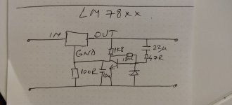
Yes you add 100R between the GND leg of the reg and GND of the pcb. Then that is your ADJ pin now. But you showed the denoiser. There's the dienoiser as well which pushes it even further. Just add a PNP and a resistor extra:

This is for positive rail LM78xx. For negative you switch all polarities (caps, diode) and swap PNP and NPN between them.
A few details:
The LM78xx implementation also needs the 220uF capacitor as in the upper photo. For LM317 you need to flip its polarity, and you need to keep track of this when doing the negative. Very easy to get confused. For example I used LM317+dienoiser for positive and LM7912 +dienoiser for negative.
LM337+dienoiser for negative is not stable. LM79xx+dienoiser aparently works with only 20nF Ccomp. If you ask me I'd go for LM7x12 +dienoiser for both rails on this dac. LM317+dienoiser is stable in my case with 40nF Ccomp. 20nF seems to be good enough for LM7x12+dienoiser.
Also for LM3x7 the 220uF cap needs to have a similar voltage rating to the output voltage. For LM7x12 the 220uF can be 6.3V rating as there's low voltage across it. That means you can even get away with 1206 in that spot, and it can be installed instead of the smd electrolytic on the latest pcb I made on that thread.
22uF needs to have a larger than reg output voltage rating on all designs and regulators used with the de/dienoiser.
R3 in the above schematic has to be adjusted according to the output voltage for best performance.
For the LM3x7+dienoiser you have the recommended values here:
D-Noizator: a magic active noise canceller to retrofit & upgrade any 317-based V.Reg.
And for the LM78xx/79xx you have the table of values in this post:
D-Noizator: a magic active noise canceller to retrofit & upgrade any 317-based V.Reg.
Ignore the 220uF polarity shown in the 78xx/79xx post with tables for resistor values, it's put wrong there.
I have uploaded the LTSpice sim which has lm317 and lt1117 variable and fixed so you can play with it.
Also you transform a dienoiser into a denoiser by shorting this R3 resistor from my schematic. Its value is also a bit different if using the dienoiser with 1117.
The 1117 variable reg is interesting. While there is a lm317 in sot-223, the 1117 has a more linear output impedance even if the lm317 is a good bit lower in the lower part of the audio spectrum, which would help with the rectifier ripple. But that is helpful as a first stage regulator. Having it after let's say lm7812 then I think linearity is more important, for example on our pcb where its used for VACC/Vref. I don't know if I'll replace the 1117-5.0 with a variable 1117 or lm317. Still thinking. Both lm317 or variable output 1117 give better results than fixed voltage 1117 (all with dienoiser of-course).
Attachments
Last edited:
Also important detail to add. For best results it's recommended you sense the regulator output at loading point. That means you install the add-on pcb close to the load, and keep short sense wires. The ADJ signal wire is higher impedance and can be ran longer without pickup issues.
In my case I tapped the +/gnd from the input of the ams1117-5.0 used for VACC and -/gnd at output opamp capacitor.
Also important note: lm317 does not like low esr caps on the output. You need to be around 0.2R for it. Don't go lower or you might get instabilities. I just replaced the output caps on both rails with a Panasonic FC 100uF/63V which has the ESR in this area. Considering the performance of the dienoiser I don't think it's necessary to go high capacitance with ultra low esr caps.
Last edited:
How many people actually try the various denoiser options, then listen for audible results each time?
Also, the old Wenzel versions may sometimes do what is needed just fine.
Doing just the +-12V rails might not reveal much but doing VACC/Vref seems to lead to a pretty significant change in the case of this DAC.
I'm curious if anyone goes for the 5V on VACC/Vref.
Also, the old Wenzel versions may sometimes do what is needed just fine.
Are you talking about the one with an opamp? I see an extra electrolytic as well. The opamp needs its power rails as well. Try getting all that into this pcb size that I used for AVCC/Vref:

I was talking about sometimes well-tuned rather more elegant designs may sound better than more complex ones for AVCC, or for Vref. Why exactly remains to be shown. Question was if anybody is actually doing the listening comparisons to help find out.
We are talking about retrofitting an existing implementation that uses a single ams1117-5.0 that feeds AVCC/Vref.
What would be a well-tuned rather more elegant design in comparison with the one I am proposing? How is it not elegant for a few resistors, three caps and two bjt? Did you check the 15uOhm output impedance at 100Hz? Or the around -47dB extra PSRR from a regular lm317 implementation?
Great miniaturisation! What smd transistors did you used? What smd size for resistors/caps?
Seems that best results were with ZTX851/ZTX951 but I think those are tht only. Best ratio of price/performance seems to be bc337/bc327. The smd equivalent for bc337/bc327 is bc817/bc807 and that is what I used. The package is sot23.
All resistors are 0805. For the comp cap I sandwiched two 10nF 0805 caps and for the 22uF cap I sandwiched two 10uF/10V caps. The 220uF cap is 6.3mm by 5mm tall. The 220uF footprint seems to just barely fit a 1206 if you can find/have one. For the LM7812/7912 you'd need 16V rating for the 22uF cap. The 220uF can be as low as 6.3V if you're using LM7812/7912 and you do not switch to LM317/LM337 (LM337+dienoiser doesn't work anyway, only with denoiser. LM7912+dienoiser gives lower noise floor than LM337+denoiser).
I used 0805 for the 22uF cap because I had 10uF/10V in that format and I used that board for the 5V rail. I made a tht version for the lm7812/7912. But I might make two individual small boards that I could place as close to the load as possible. The sense V/GND lines should be as short as possible for best results.
This is how I mounted it near the DAC chip:


Trileru,
No intention to come off as critical of what you are considering. Merely trying to suggest that you may or may not make the dac sound better. If the goal were to make something measure better, that would be a different question from my point of view. So, what I would like when you are done trying whatever it is you want to do, if you would tell us if in your opinion the sound is improved, more or less the same, or maybe even worse. It could happen that some noise lowering circuits sound better than others. In fact, that is what I am finding (in some cases much to my surprise). I don't know exactly why that is, and I'm not ready to start throwing out any theories yet.
No intention to come off as critical of what you are considering. Merely trying to suggest that you may or may not make the dac sound better. If the goal were to make something measure better, that would be a different question from my point of view. So, what I would like when you are done trying whatever it is you want to do, if you would tell us if in your opinion the sound is improved, more or less the same, or maybe even worse. It could happen that some noise lowering circuits sound better than others. In fact, that is what I am finding (in some cases much to my surprise). I don't know exactly why that is, and I'm not ready to start throwing out any theories yet.
I've done this modification to the Magni headamp and there were subtle differences. Especially at lower volume, I could perceive a more detailed bass. That was my impression. Then I've done it to the +-12V rails of the DAC but I only had about a day or so before doing the AVCC/Vref mod. I couldn't quite make an opinion if that changed anything. But! After doing AVCC/Vref well that was completely something else. It's strange as it's the first time when I made a mod and the sound changed this much.
I will not go into details as I'm still getting used to it but for me this is something else. I personally think that "lower tier" dac chips should get a good analog implementation before being judged. Especially a clean Vref. Tempco/drift/accuracy are not that important on this chip. Low noise and low output impedance of the regulator feeding it is what makes it shine.
I'm genuinely curious about the opinion of the first person that does this mod to this particular DAC. Personally for me it seems the mod clearly moves this dac to a higher tier. I have no doubt about that. I like everything about what I hear from it.
Ah another thing, loud music is not as annoying as it was before. I'm not sure why. I realized today that yesterday I listened to music way louder that I usually do. Usually I wouldn't because I didn't enjoy it but I kinda got carried away with yesterday's listening session and didn't really notice how loud it was. I'm not sure if that counts for anything.
Also I did realize that I was looking for detailed music to notice differences then it hit me that that might add subjectivity to the matter as I usually am not looking specifically for very detailed music. I just let it roll, listen to podcasts etc. So then I tried to not focus on what I listen to and let it roll. But all through yesterday I constantly was interrupted about the thought of "wait, this is very different in a very pleasant way'. That's why I decided to share this on this thread. Seems like a something people might want to try.
I am not debating that different denoisers or topologies for Vref wouldn't sound different. For me this is a surprise I didn't expect. It could be. But I am more interested in understanding why from a technical point of view. So far my opinion is that the low output impedance makes for a smaller sag of the supply for Vref and AVCC which helps with channel separation. The lower noise also allows for fine details to not be lost. There may be "flavors" of sound at this level as well, I'm just getting used to the level so to speak. It's new to me.
That you found yourself listening loud, and it didn't bother you is an effect I have experienced as well. I think it could be due to reduced distortion. A voltage regulator commonly has an error amplifier, the linearity of which could affect the sound. Also, I have seen some people that think frequency and phase response can matter too. Those things can be linear distortions that may have a sound. Humans have been found to be insensitive to phase when it is constant, but when it is changing it gets a lot more noticeable. The change could be relative too: Various people have suggested a singer perming a glissando though a stationary but rapid phase shift may sound odd. Also, the dac output is typically multiplied by Vref. Thus, however it sounds will be imprinted on the audio. Some people may notice, others not.
Last edited:
I will try other solutions as now I'm curious but I need some time to adjust to the way it sounds now. Else I won't be able to draw meaningful conclusions. Changing many things in a short period makes it hard to understand what did what to the resulting sound.
Another detail that I noticed is that I am more aware of the rooms that certain videos I watch are recorded in. Happened a few times, it's pretty obvious when it comes to rooms. It's like there's some fine details that help with better defining the environment.
Another detail that I noticed is that I am more aware of the rooms that certain videos I watch are recorded in. Happened a few times, it's pretty obvious when it comes to rooms. It's like there's some fine details that help with better defining the environment.
I agree it can be tricky to experiment. My best dac clocks take 3-days to fully warm up and stabilize at lowest jitter. At least, jitter is my assumption. Whatever it is, there is a related audible effect. As a result, I have two Vref supplies: A standard one, and the one I am working on. I switch between them and and take away the experimental one for modification work. That way I can leave the clocks running at all times to remove them as a variable.
I see that the CS8416 receiver is fed from the analog supply as well. This is from the receiver datasheet:
"Analog Power (Input) - Analog power supply. Nominally +3.3 V. This supply should have as little noise as possible since noise on this pin will directly affect the jitter performance of the recovered clock"
So ideally I'd address this rail as well. Kind of tricky at 3.3V as the denoiser ups the voltage a bit, but I could either use a 2.85V ams1117 either the adjustable version for 3.3V output. I don't have any at hand and I want to wait for some time to adjust to the way the DAC sounds now, and notice any differences for that rail as well.
I also see that the DAC has no external clock. Any gains to be had with CS8416 adding one? I think it would be fed to OMCK pin 25.
Do you measure your clock performance?
IME, clean power for PLLs tends to be helpful. I don't use CS8416, but I do use AK4137 which can use a reference clock for the PLL. IME, its helpful to have a good reference clock for that chip.
Regarding measurement of clocks, many people believe that close in phase noise is a critical factor for audio DAC performance. Unfortunately, it takes specialized equipment to measure it. What everybody measures because its cheap and easy, and can show some types of problems, is J-test. There is a paper by the creator of the test, Julian Dunn, that describes how it works. Its good for finding deterministic jitter problems, but not very useful for close in phase noise. One can get kind of a rough idea in relative terms by looking at the width at the base of the J-test peak in an FFT.
Many people find that best sound quality in terms of clocking comes from either asynchronous USB, of from FIFO reclocked SPDIF family inputs. Clocking a DAC from a PLL recovered SPDIF clock is always going to give more close-in phase noise than a good crystal clock. Also perhaps worth keeping in mind, jitter affects the sound of different DAC architectures in different ways. Some architectures are known to be more sensitive than others, even down very specific aspects of different SD DAC architecture subtypes.
In terms of the role of measurements in what I do, they are good for checking for problems, but not for deciding if something sounds good or not. Some people think measuring well and sounding good kind of starts to be two different things once one gets down to nonlinearities measuring below maybe around -110dB or so, but depending on the particular issue. For example, high order harmonic distortion (and associated IMD arising from the same nonlinearity) is more annoying to me than very low order.
For things that I am not equipped to measure, I just use my ears and those of a few people who's ears I trust. In the end its only audio, which IMHO is good if it sounds good.
Last edited:
- Home
- Source & Line
- Digital Line Level
- DAC 2496 (AK4393) DAC KIT With CS8416+AK4393+5532