Thanks for all the work.... this thread has rekindled my interest in DACs.
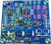
ClaveFremen, I believe the short connection between C9 and L1 is in error. This version looks a lot more accurate than the original posting.
You're welcome
")
Yep!, you're right, I've attached an updated version.
BTW: I notice that there are a least 3 versions of this PCB so far and I know from experience that there is a difference in "quality" between various suppliers of this kit.
I am not so sure about how to identify boards uniquely.. certainly not when we deal with a multitude of Chinese suppliers, world-wide.
3 Versions???
From what I saw there only 2 PCB versions: the first (green PCB) and the last one (blue PCB).
The difference should be only color, some markings (1800uF caps vs 2200uF, 7815/7915 vs 7812/7912) and lead spacing (C38, C39)
Though different vendors use different passives (particularly caps).
I am a little concerned that in the thread wrong filtering appears to have been identified on some boards (4396 filtering not the same as 4393 filtering, thanks to ClaveFreman).
Simply all 2 PCBs are designed for AK4393, if AK4396 is used LPF should be adapted but it's not.
Attachments
i think each ak4396 dac kit seller in ebay uses different kinds or brands of capacitor? see the pictures in ebay if i am wrong? there are i think 3 versions???
Yes, you're right. I'm talking about PCBs.
There are 2 PCB versions but if we consider also passives selection more versions are available.
Assembled DAC Boards
Hi,
I have located a green PCB, in the assembled category ( at Assembled DAC 2496 (AK4396) CS8416 DAC With Transformer | eBay UK ). Also at Assembled DAC 2496 (AK4396) CS8416 DAC Board 24BIT 192K | eBay UK
They do all appear to be very similar... but we are assuming the the photos actually show their current product. Could these be stock photos and we don't know what we actually get until we receive it?
different to the ebay listing image .
This is true as Erin and I bought our DAC's at the same time from the same supplier and they came with different components different to the image on the ebay listing .
I bought another DAC because the prior one had a receiver chip failure this was a AK4396 DAC and it also was different to the ebay listing image .
I bought this second DAC assembled as I was sick of the failure rate I had with these DAC's (both with the same receiver chip failure and also a grounding issue) and so far so good .
Hi,
I have located a green PCB, in the assembled category ( at Assembled DAC 2496 (AK4396) CS8416 DAC With Transformer | eBay UK ). Also at Assembled DAC 2496 (AK4396) CS8416 DAC Board 24BIT 192K | eBay UK
They do all appear to be very similar... but we are assuming the the photos actually show their current product. Could these be stock photos and we don't know what we actually get until we receive it?
This is true as Erin and I bought our DAC's at the same time from the same supplier and they came with different components different to the image on the ebay listing .
I bought another DAC because the prior one had a receiver chip failure this was a AK4396 DAC and it also was different to the ebay listing image .
I bought this second DAC assembled as I was sick of the failure rate I had with these DAC's (both with the same receiver chip failure and also a grounding issue) and so far so good .
Random DAC Boards
Great,
so to add to the fun of DIY, we do not actually know what we have purchased until it arrives.
Basically for me that means that I cannot pre-purchase any upgrade components because I have no idea what componants are supplied.... and also probably no idea of the actual circuitry on the pcb!
And then, to make it even more interesting, we have threads like this (very useful of course) discussing changes to boards.. but we don't actually know precisely which board anyone is talking about!
I must admit that I am not too unhappy with this as it does add some interest, and this particular DIY kit is pretty cheap if it all goes pear-shaped. It would not be so interesting on high-power systems ... let the buyer beware is still good advice.
Basically for me that means that I cannot pre-purchase any upgrade components because I have no idea what componants are supplied.... and also probably no idea of the actual circuitry on the pcb!
And then, to make it even more interesting, we have threads like this (very useful of course) discussing changes to boards.. but we don't actually know precisely which board anyone is talking about!
No, it's easier than that....
Simply buy all passive components
Some are not bad (like Nichicon PWs) but all of them have better counterparts...
Just look at mine, I've replaced quite all... with great results.
Hi,
I was slightly tongue-in-cheek with my comments, but I think there can be nasty surprises when we are not completely sure of the various pcb versions around.
I am hoping to incorporate most, if not all, of the upgrades that you have listed in the spreadsheet.. specifically with the 4396 chip (with the appropriate filtering). I also want to try a direct feed from the output pins of the chip itself ... as I have done on some other AKM devices, with some success.
One column that would be nice to add to the spreadsheet would be something that gives an idea of how useful / significant you felt the particular upgrade to be. It is hard to have a priority of implementation. Do you have a gut-feel of which changes gave the most benefit?
Do you have a gut-feel of which changes gave the most benefit?
If you have AK4396 version I consider mandatory the replacement of caps and resistors as per datasheet.
Regarding impovements the most important, in order are: LPF caps, Opamp, Opamp decoupling, DAC decoupling, LPF carbon resistors, CS8416 decoupling.
Beware that the spreadsheet was a 'proposal' subject to change as experiments are going on.
In the next days I'll post an updated one.
Hi,
One column that would be nice to add to the spreadsheet would be something that gives an idea of how useful / significant you felt the particular upgrade to be.
That would be most useful.
Oscons , KP1830's , PPS and Silmic
Oscons around the DAC/receiver and if you can get them KP1830's on the filters
PPS film (again if you can get them) bypassing on the digital electrolytic's and those massive power filter caps Erin used did get it kicking along especially the one on the digital line , some Silmics on the analogue lines preferably at the opamps but the do not fit very nicely there .
You just have to do more research on your capacitor selection so you know what is applicable where .
I would say the Silmics on the opamp make a nice upgrade to the sound
Hi,
I was slightly tongue-in-cheek with my comments, but I think there can be nasty surprises when we are not completely sure of the various pcb versions around.
I am hoping to incorporate most, if not all, of the upgrades that you have listed in the spreadsheet.. specifically with the 4396 chip (with the appropriate filtering). I also want to try a direct feed from the output pins of the chip itself ... as I have done on some other AKM devices, with some success.
One column that would be nice to add to the spreadsheet would be something that gives an idea of how useful / significant you felt the particular upgrade to be. It is hard to have a priority of implementation. Do you have a gut-feel of which changes gave the most benefit?
Oscons around the DAC/receiver and if you can get them KP1830's on the filters
PPS film (again if you can get them) bypassing on the digital electrolytic's and those massive power filter caps Erin used did get it kicking along especially the one on the digital line , some Silmics on the analogue lines preferably at the opamps but the do not fit very nicely there .
You just have to do more research on your capacitor selection so you know what is applicable where .
I would say the Silmics on the opamp make a nice upgrade to the sound
Spreadsheet
Hi,
One of the advantages of the delay in getting goods from China is that you get a chance to reflect on your plans. In this case I shall do NOTHING until I see the new spreadsheet (for which, many thanks) and I have taken on board the various opinions on priorities of update.
This will be very interesting project as I also have in my computer an X- Meridian 7.1 sound card. This board has 4 AKM4396 chips on it and user-selectable, socketed, opamps following, so I should get some interesting A-B comparison opportunities.
If you have AK4396 version I consider mandatory the replacement of caps and resistors as per datasheet.
Regarding impovements the most important, in order are: LPF caps, Opamp, Opamp decoupling, DAC decoupling, LPF carbon resistors, CS8416 decoupling.
Beware that the spreadsheet was a 'proposal' subject to change as experiments are going on.
In the next days I'll post an updated one.
Hi,
One of the advantages of the delay in getting goods from China is that you get a chance to reflect on your plans. In this case I shall do NOTHING until I see the new spreadsheet (for which, many thanks) and I have taken on board the various opinions on priorities of update.
This will be very interesting project as I also have in my computer an X- Meridian 7.1 sound card. This board has 4 AKM4396 chips on it and user-selectable, socketed, opamps following, so I should get some interesting A-B comparison opportunities.
RE: 3 types of pcb ???
Ok, I propose (just to rule out variations) that we compile some pics of the boards we've received.
I'll start here by uploading pics of the pcbs I've acquired...


I noticed on Clave's last attached picture that there's no 'ES' marking in the bottom right corner by the 'Mini 24 96' markings
My boards arrived populated, so I cannot see/confirm if there's any track route differences.
Another thought : I wonder if Evanellion can comment on these variationa as he/she said earlier in this thread that they developed the board design !?!
-Andy-
Ok, I propose (just to rule out variations) that we compile some pics of the boards we've received.
I'll start here by uploading pics of the pcbs I've acquired...
I noticed on Clave's last attached picture that there's no 'ES' marking in the bottom right corner by the 'Mini 24 96' markings
My boards arrived populated, so I cannot see/confirm if there's any track route differences.
Another thought : I wonder if Evanellion can comment on these variationa as he/she said earlier in this thread that they developed the board design !?!
-Andy-
AK 4395 IC/5v reg/Oscon mods
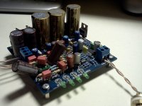
Well, I can say that after all this work, the new modifications to the
AKM kit board is completed... up an runnin' and as I type - burning in ! (Big sigh of releif)
Here's how it looks...

For a moment there, before power-up, I was thinking that the chip could be a fake as the labelling isn't the same as the original AK4396 ic..
..but all appears to be working well

{This pic shows the extra voltage regulator used to dial-in the 5v required by the 4395 i.c}
I'll run this in for the next 4-5 days then give it a spin thru the stax headphones. Hopefully, it'll be a blissfull experience
-Andy-
Well, I can say that after all this work, the new modifications to the
AKM kit board is completed... up an runnin' and as I type - burning in !
(Big sigh of releif)Here's how it looks...
For a moment there, before power-up, I was thinking that the chip could be a fake as the labelling isn't the same as the original AK4396 ic..
..but all appears to be working well
{This pic shows the extra voltage regulator used to dial-in the 5v required by the 4395 i.c}
I'll run this in for the next 4-5 days then give it a spin thru the stax headphones. Hopefully, it'll be a blissfull experience
-Andy-
Last edited:
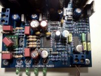
I am a little in advance...
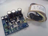
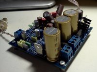
Well, I've attached an updated BOM which reflects what I've actually done and some of the planned mods and also some photos.
It includes preliminary subjective listening impressions and like the previous one it's a work in progress.
Listening impressions of mods are compared to my original assembled kit (photo attached)
The most important mods are the one regarding the LPF (Caps, resistors, opamp, opamp decoupling)
Digital chips decoupling comes immediately after.
As Jean-Paul pointed out the 7812 needs an heatsink.
Apart opamp decoupling caps all electrolythics I've used are a perfect fit. Some Wimas though must be mounted on the other side of the PCB.
In the last photo opamp decoupling caps are removed just for better visibility of others mods
Attachments
Last edited:
BOM
Hi Cleve,
that new BOM looks really useful... and the photos help a lot too. And Chrome has started to work properly! Must be a good omen. I am looking forward impatiently to the arrival of my board.
Once again, thanks for the time and effort that you have put into this
Georgevb
Hi Cleve,
that new BOM looks really useful... and the photos help a lot too. And Chrome has started to work properly! Must be a good omen. I am looking forward impatiently to the arrival of my board.
Once again, thanks for the time and effort that you have put into this
Georgevb
- Home
- Source & Line
- Digital Line Level
- DAC 2496 (AK4393) DAC KIT With CS8416+AK4393+5532