
It depends on your definition of "small": to be effective, it has to be in the region of √ (L/C), and it could result in a significant voltage drop and increase of the internal resistance. Parallel damping is another option, but it comes with problems of its ownWouldn't a small series R solve that?
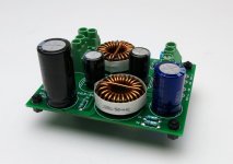
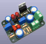
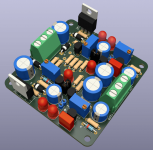
Here is a 4-pole LPF I built, to eliminate HF noise on a DC supply; its performance was quite satisfactory. Parallel damping was chosen, to reduce in-to-out series resistance. Max current was 8A, max voltage was 48V DC. Total resistance in to out was 30 milliohms.
This PCB turned out to be merely an intermediate milestone, along the pathway that led to the [dual mono] PSFILT card for the Ship Of Theseus amplifier project.
_
This PCB turned out to be merely an intermediate milestone, along the pathway that led to the [dual mono] PSFILT card for the Ship Of Theseus amplifier project.
_
Attachments
Would this be a good compromise on startup swing?

Just added a diode across the denoiser coupling cap. This requires to tweak R3/R10 so as to bring the denoiser DC point close to the base of Q2/Q5 voltage, ideally within +/- half Vdrop. This diode's Vdrop determines kinda the max swing it allows on the output (1/2Vdrop on the upper swing).
In this example I have two different outputs, 5V and 12V, and am comparing to the original Denoisator's startup swing for both these voltages. The CCS exacerbates the startup swing.
I have simulated it for both MPSA06 and ZTX851 and there's a comfortable range for R3/R10 as long as you can tweak this value.
I don't know if it's actually working, simulation seems to indicate so. The lower the Vdrop the lower the output swing, but requires more R3/R10 precision. Schottky/1n4148/LED seem to work. The LED would be off unless something's wrong?
edit: as long as R3/R10 are in the correct range then performance shouldn't be affected vs no diode version.
Last edited:
This doesn't seem to work in LTSpice, still bad tempco.
Here's an example of how to do it for ZTX851/BC337 which have similar tempco. MPSA06 seems better from simulation.
We basically need to contain the difference in denoiser circuit DC voltage between 25-75 degrees C into that half Vdrop window. As long as it lands in there then we get a reduction in startup swing and no other performance aspect is affected.
With lower tempco BJTs for the denoiser circuit the larger this area is.
As far as diode type to use, LEDs seem to simulate good, and offer a large enough window even for ZTX851/BC337.
Considering this example for 5Vout and 12Vout:

I used the LM317 model included in LTSpice as the LM317N model I used before does not work very good with higher temperatures.
For 5Vout I used a single red LED but three 1n4148 diodes in series seem to work similarly. For ZTX851 we have a usable range of 43k-55k for R3, and a full sweep of this range at 25-50-75 degrees C looks like this, compared to the NoNoiser that Elvee originally posted.

The highest swings are at 75degrees C. Choosing a middle value for R3, say 49K then at 25 degrees C the output looks like this:

That looks like a pretty nice reduction in startup swing using only a single LED, that will light up briefly at startup, it should stay off after.
The 43k-55k range is a set of possible values where performance of the circuit is not affected, between 25 and 75 degrees C of operation. But this will likely vary with BJT gain variation. It might be possible to have a standard resistor value for R3 which will cover BJT gain variations but this should be tested.
For MPSA06 simulation shows tighter tempco so should be simpler to use, BC337 should be similar to ZTX851.
Here's how the voltage looks across the LED at full usable range sweep between 25-75degrees C

All possible values for the useful R3 range fit well in this half of Vdrop window. It doesn't go under 0V so as to not reverse bias the coupling capacitor. This way tempco is not altered with this mod.
For 12Vout I used two red LEDs in series and with ZTX851 possible R23 range seems to be 180K-188K and for a full temperature sweep the output looks like this compared to the original NoNoiser:

If we choose a value for R23 in the middle of that range then the output looks like this:

Which is pretty decent. The range is smaller and small chances of getting a standard resistor value, but as long as you are willing to tweak this resistor value you could lower the startup swing with using 1-2 diodes in series. There's LEDs with higher Vdrop, I think white LEDs with around 3Vdrop. I might test to see if this works in reality.
Here's the voltage across the two LEDs with a sweep of usable R23 range at 25-75 degrees C:

Again you see this 180K-188K R23 range offers good conditions of operation, this voltage is between 0V and half Vdrop.
This mod doesn't seem too restrictive for R3/R23 and still lowers startup swing, and we could theoretically get away with using just one or two diodes.
We basically need to contain the difference in denoiser circuit DC voltage between 25-75 degrees C into that half Vdrop window. As long as it lands in there then we get a reduction in startup swing and no other performance aspect is affected.
With lower tempco BJTs for the denoiser circuit the larger this area is.
As far as diode type to use, LEDs seem to simulate good, and offer a large enough window even for ZTX851/BC337.
Considering this example for 5Vout and 12Vout:
I used the LM317 model included in LTSpice as the LM317N model I used before does not work very good with higher temperatures.
For 5Vout I used a single red LED but three 1n4148 diodes in series seem to work similarly. For ZTX851 we have a usable range of 43k-55k for R3, and a full sweep of this range at 25-50-75 degrees C looks like this, compared to the NoNoiser that Elvee originally posted.
The highest swings are at 75degrees C. Choosing a middle value for R3, say 49K then at 25 degrees C the output looks like this:
That looks like a pretty nice reduction in startup swing using only a single LED, that will light up briefly at startup, it should stay off after.
The 43k-55k range is a set of possible values where performance of the circuit is not affected, between 25 and 75 degrees C of operation. But this will likely vary with BJT gain variation. It might be possible to have a standard resistor value for R3 which will cover BJT gain variations but this should be tested.
For MPSA06 simulation shows tighter tempco so should be simpler to use, BC337 should be similar to ZTX851.
Here's how the voltage looks across the LED at full usable range sweep between 25-75degrees C
All possible values for the useful R3 range fit well in this half of Vdrop window. It doesn't go under 0V so as to not reverse bias the coupling capacitor. This way tempco is not altered with this mod.
For 12Vout I used two red LEDs in series and with ZTX851 possible R23 range seems to be 180K-188K and for a full temperature sweep the output looks like this compared to the original NoNoiser:
If we choose a value for R23 in the middle of that range then the output looks like this:
Which is pretty decent. The range is smaller and small chances of getting a standard resistor value, but as long as you are willing to tweak this resistor value you could lower the startup swing with using 1-2 diodes in series. There's LEDs with higher Vdrop, I think white LEDs with around 3Vdrop. I might test to see if this works in reality.
Here's the voltage across the two LEDs with a sweep of usable R23 range at 25-75 degrees C:
Again you see this 180K-188K R23 range offers good conditions of operation, this voltage is between 0V and half Vdrop.
This mod doesn't seem too restrictive for R3/R23 and still lowers startup swing, and we could theoretically get away with using just one or two diodes.
Attachments
Last edited:
Ok so I tried this out and seems to be working fine. I measured this configuration with the same exact parts/values, but with a regular LM317:

And I think I now understand why the DC-coupled version performs so well. It is because it tried to keep 1.25V between Vout and denoiser output so then R3 is "maxed out" in that setup. The CCS needs at least around 1V-1.2V across it so performance is not affected, and that's kind of a happy coincidence which pushes the BJT gain as much as possible in that setup.
When I previously measured different setups I never really considered R3 that much, I just found a value that worked and it got inherited between different BJTs which led to bad results. Adjusting this value for each BJT is very important for the performance of the circuit.
This LED bypass mod requires to also bring denoiser DC voltage up close to Q2's base level. In this AC coupled circuit there's always around 1.8V between base of Q2 and Vout. If we match this level then there's 1.8V across the CCS which means it's close to the DC-coupled version from this point of view, and this turns up the performance of the BJT.
It also seems in this configuration there's no need for the R in compensating network, the circuit was stable with just 2.2nF (measured 2.4nF might be a 4.7nF). Also I didn't use the ferrite bead and everything seemed stable. Would recover fast after poking with metal tweezers.
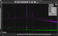
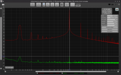
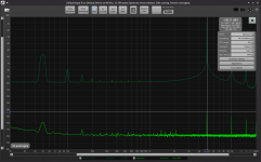
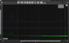
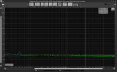
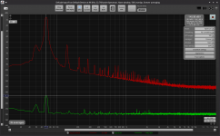
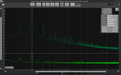
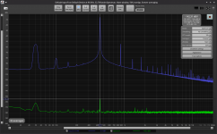
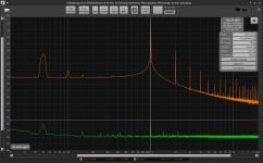
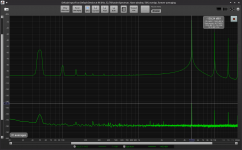
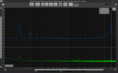
Performance with ZTX851 really surprised me, around 150dB of PSRR between 100Hz and 1kHz, still over 110dB at 15kHz. Noise came out at around 45nV total which is crazy low. MPSA06 performed similarly but a bit worse, 2-3dB lower PSRR and 72nV noise. Still incredibly good performance, just not as good as ZTX851.
Measurements were done with a regular LM317 from ST, nothing special. LM317N from TI had 2-3dB better PSRR, same noise floor.
Actual R3 value in my measurements differs from simulation. I needed 149K to get around 0.15V across C3, denoiser side more negative. If I remember correctly heating Q1 with soldering iron made for denoiser voltage to drop few hundred mV. Having around 0.15V across C3 gives us few hundred mV for tempco variation. If it heats up by a lot then this difference will increase until it reaches Vdrop of D4 at which point the LM317 gets DC-coupled to the denoiser, and denoiser begins to affect Vout, which will start falling depending on temperature, but I think this is valid at very high temperatures, I wouldn't run it in those conditions anyway.
Being just a bit over 0V, say 0.15V at lowest operating temperature means it will never reverse bias the capacitor with increase in temperature.
If we make the denoiser side more positive we start getting higher ripple, and we can't go up too much as we start to affect the CCS performance. There seems to be a sweet spot where we get a reduction in startup swing and the rest of the performance is not affected but you have to adjust R3 manually to reach this point which depends on BJT gain. Tweaking R3 is good for the overall performance of the circuit anyway.
The only downside to maximizing the gain is a very high startup swing. Without the LED mod, with MPSA I measured 14.4V on the output on the first swing. This swing is related to R3 and C4 and the gain of the denoiser circuit and if you max it out you need to use the LED mod to seriously limit the startup swing. With the LED mod installed and R3 tweaked I got 12.4V max swing instead of 14.4V.
I also tried 3x1n4148 diodes in series and worked the same. If using an LED it will turn on at startup but very dim and will slowly fade out.
I think this might be this circuit's final form. I didn't try the "dienoiser" configuration as I really don't see a need for it, and this simpler form seems stable with just let's say 3.3nF.
I attached the measurements. My LNA adds around 62nV of noise to the noise measurement.
edit: this is what startup simulation looks like for this circuit with vs without the LED mod:

And I think I now understand why the DC-coupled version performs so well. It is because it tried to keep 1.25V between Vout and denoiser output so then R3 is "maxed out" in that setup. The CCS needs at least around 1V-1.2V across it so performance is not affected, and that's kind of a happy coincidence which pushes the BJT gain as much as possible in that setup.
When I previously measured different setups I never really considered R3 that much, I just found a value that worked and it got inherited between different BJTs which led to bad results. Adjusting this value for each BJT is very important for the performance of the circuit.
This LED bypass mod requires to also bring denoiser DC voltage up close to Q2's base level. In this AC coupled circuit there's always around 1.8V between base of Q2 and Vout. If we match this level then there's 1.8V across the CCS which means it's close to the DC-coupled version from this point of view, and this turns up the performance of the BJT.
It also seems in this configuration there's no need for the R in compensating network, the circuit was stable with just 2.2nF (measured 2.4nF might be a 4.7nF). Also I didn't use the ferrite bead and everything seemed stable. Would recover fast after poking with metal tweezers.
Performance with ZTX851 really surprised me, around 150dB of PSRR between 100Hz and 1kHz, still over 110dB at 15kHz. Noise came out at around 45nV total which is crazy low. MPSA06 performed similarly but a bit worse, 2-3dB lower PSRR and 72nV noise. Still incredibly good performance, just not as good as ZTX851.
Measurements were done with a regular LM317 from ST, nothing special. LM317N from TI had 2-3dB better PSRR, same noise floor.
Actual R3 value in my measurements differs from simulation. I needed 149K to get around 0.15V across C3, denoiser side more negative. If I remember correctly heating Q1 with soldering iron made for denoiser voltage to drop few hundred mV. Having around 0.15V across C3 gives us few hundred mV for tempco variation. If it heats up by a lot then this difference will increase until it reaches Vdrop of D4 at which point the LM317 gets DC-coupled to the denoiser, and denoiser begins to affect Vout, which will start falling depending on temperature, but I think this is valid at very high temperatures, I wouldn't run it in those conditions anyway.
Being just a bit over 0V, say 0.15V at lowest operating temperature means it will never reverse bias the capacitor with increase in temperature.
If we make the denoiser side more positive we start getting higher ripple, and we can't go up too much as we start to affect the CCS performance. There seems to be a sweet spot where we get a reduction in startup swing and the rest of the performance is not affected but you have to adjust R3 manually to reach this point which depends on BJT gain. Tweaking R3 is good for the overall performance of the circuit anyway.
The only downside to maximizing the gain is a very high startup swing. Without the LED mod, with MPSA I measured 14.4V on the output on the first swing. This swing is related to R3 and C4 and the gain of the denoiser circuit and if you max it out you need to use the LED mod to seriously limit the startup swing. With the LED mod installed and R3 tweaked I got 12.4V max swing instead of 14.4V.
I also tried 3x1n4148 diodes in series and worked the same. If using an LED it will turn on at startup but very dim and will slowly fade out.
I think this might be this circuit's final form. I didn't try the "dienoiser" configuration as I really don't see a need for it, and this simpler form seems stable with just let's say 3.3nF.
I attached the measurements. My LNA adds around 62nV of noise to the noise measurement.
edit: this is what startup simulation looks like for this circuit with vs without the LED mod:
Attachments
-
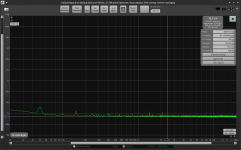 noise_12V_regular_lm317_ztx.png41 KB · Views: 81
 -
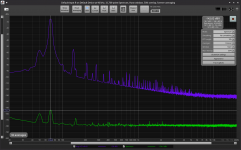 70hz_ztx_regular_LM317.png71 KB · Views: 86
 -
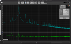 105hz_ztx_regular_LM317.png68.3 KB · Views: 87
 -
 440hz_ztx_regular_LM317.png60.7 KB · Views: 85
 -
 1000hz_ztx_regular_LM317.png56.9 KB · Views: 75
 -
 5000hz_ztx_regular_LM317.png54 KB · Views: 75
 -
 15000hz_ztx_regular_LM317.png48.9 KB · Views: 82
Last edited:
I made measurements for 5Vout version using these values:

Just that R3 was actually 39.4K to get 50mV across D4, which was a 1n4148. I set the output for 5.00V, without the diode the first swing would go to 6.00V and with the diode it goes to 5.08V max.
Measurements were done with a regular LM317 from ST, I tried the LM317N and gets 3dB or so better PSRR, same noise.
Noise remained similar vs 12Vout. PSRR decreased a bit by 6-7dB, performance is still very good even at 5Vout.
Attachments
-
 noise_5V_regular_lm317_ztx.png35.9 KB · Views: 80
 -
 70hz_ztx_regular_LM317_5V.png71.4 KB · Views: 73
 -
 105hz_ztx_regular_LM317_5V.png67.2 KB · Views: 71
 -
 440hz_ztx_regular_LM317_5V.png59.6 KB · Views: 80
 -
 1000hz_ztx_regular_LM317_5V.png57.4 KB · Views: 77
 -
 5000hz_ztx_regular_LM317_5V.png52.8 KB · Views: 66
 -
 15000hz_ztx_regular_LM317_5V.png50.7 KB · Views: 78
Simulation also shows that this could work for 3.3Vout as well, and seems to work with 5Vin:

PSRR seems to be a bit lower than 5Vout, kind of the same difference between 12V and 5V:

And startup swing should be lower than 3.4V, with 1n4148 diode:

One detail that I forgot to account for is adjusting C14 from the schematic I attached at the top of this post. Varying R15 would imply to alter C14 to keep the same LF response. For 3.3Vout it would need to be around 470uF, and for 5Vout around 220uF.
edit: PSRR is a bit optimistic from simulation as it uses a more performant LM317 variant, some sort of military grade part. Shave 10-15dB from simulation to get closer to reality.
PSRR seems to be a bit lower than 5Vout, kind of the same difference between 12V and 5V:
And startup swing should be lower than 3.4V, with 1n4148 diode:
One detail that I forgot to account for is adjusting C14 from the schematic I attached at the top of this post. Varying R15 would imply to alter C14 to keep the same LF response. For 3.3Vout it would need to be around 470uF, and for 5Vout around 220uF.
edit: PSRR is a bit optimistic from simulation as it uses a more performant LM317 variant, some sort of military grade part. Shave 10-15dB from simulation to get closer to reality.
Last edited:
Made the measurements for the negative LM337 version, both 5Vout and 12Vout. Good news all around!
Seems like the ferrite bead increases the noise floor so I removed it, same compensation network, 2.4nF (might be a 2.2nF or 2.7nF), no R, and this time it seems LM337 is stable also without that Panasonic FR cap, I used a random Rubycon ZLH 330uF/35V which is low ESR and worked fine. This Rubycon cap is short and stubby.
The exact circuits I measured were these:


I did not adjust C5 for 5Vout, left it at 100uF. I tweaked Vout at -5.00V and -12.00V and with D4/D8 installed I had highest swings at startup of -5.073V and -12.44V. For 5V diode had 60mV across it and for 12Vout LED had 250mV across it. Without the diodes installed I had -5.95V and -14.9V on first swing. So the performance comes at a price with the higher first swing, but this can be mitigated with the diode.
Performance was similar to LM317. I used a ST LM337 marked LM337SP. Same noisefloor as LM317. A bit lower HF PSRR, but still good.
I guess this configuration solves all of the previous issues. And you can get +/-5V with very low noise out of LM3x7.
So now it's stable, great performance and no need for certain output capacitors, make sure it's around 0.2R ESR for LM317 and around 0.05R for LM337.
I attached the measurements. I'll post updated PCB designs that will be optimized for this configuration.
Seems like the ferrite bead increases the noise floor so I removed it, same compensation network, 2.4nF (might be a 2.2nF or 2.7nF), no R, and this time it seems LM337 is stable also without that Panasonic FR cap, I used a random Rubycon ZLH 330uF/35V which is low ESR and worked fine. This Rubycon cap is short and stubby.
The exact circuits I measured were these:
I did not adjust C5 for 5Vout, left it at 100uF. I tweaked Vout at -5.00V and -12.00V and with D4/D8 installed I had highest swings at startup of -5.073V and -12.44V. For 5V diode had 60mV across it and for 12Vout LED had 250mV across it. Without the diodes installed I had -5.95V and -14.9V on first swing. So the performance comes at a price with the higher first swing, but this can be mitigated with the diode.
Performance was similar to LM317. I used a ST LM337 marked LM337SP. Same noisefloor as LM317. A bit lower HF PSRR, but still good.
I guess this configuration solves all of the previous issues. And you can get +/-5V with very low noise out of LM3x7.
So now it's stable, great performance and no need for certain output capacitors, make sure it's around 0.2R ESR for LM317 and around 0.05R for LM337.
I attached the measurements. I'll post updated PCB designs that will be optimized for this configuration.
Attachments
Last edited:
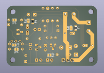
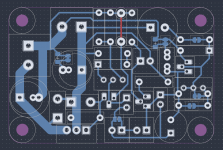
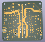
I updated the PCB designs to reflect the latest optimizations. There's greater flexibility in setting denoiser's DC point:

You can either use R10 in series with R11, either both R9/R10 in parallel without R11, either just R11.
For the swing limiting diode you have two LED footprints in series and you can short one out.
R12 as protection resistor is included but can be shorted out, this resistor worsens performance. I also included R6 with a bridged jumper, normally shouldn't be used but I left it just in case. This resistor and and a 0805 footprint in series with the output cap are the only SMD parts, which normally shouldn't be used. All boards are full THT design now.

R2 and R5 are in parallel so it's easier to set the output voltage.
J1 is a THT jumper that you can use to disconnect the denoising circuit so you can more easily set Vout and tweak denoiser DC operating point.
There's also a two pin header footprint next to the coupling capacitor, which is connected to each pin of the coupling capacitor.

You connect your multimeter probes to those points and tweak the left pot to set denoinser DC point.
All boards are single sided and DIY-able. Singles have one top side passing and dual has two. If you DIY it you need to add this wire.
BJT footprints are for BC337/BC327 which are compatible with ZTX851/ZTX951.
Board sizes are 54mm X 36mm for singles and 61mm X 59mm for the dual one.
I have not tested any of these boards so you make them at your own risk.
You can either use R10 in series with R11, either both R9/R10 in parallel without R11, either just R11.
For the swing limiting diode you have two LED footprints in series and you can short one out.
R12 as protection resistor is included but can be shorted out, this resistor worsens performance. I also included R6 with a bridged jumper, normally shouldn't be used but I left it just in case. This resistor and and a 0805 footprint in series with the output cap are the only SMD parts, which normally shouldn't be used. All boards are full THT design now.
R2 and R5 are in parallel so it's easier to set the output voltage.
J1 is a THT jumper that you can use to disconnect the denoising circuit so you can more easily set Vout and tweak denoiser DC operating point.
There's also a two pin header footprint next to the coupling capacitor, which is connected to each pin of the coupling capacitor.
You connect your multimeter probes to those points and tweak the left pot to set denoinser DC point.
All boards are single sided and DIY-able. Singles have one top side passing and dual has two. If you DIY it you need to add this wire.
BJT footprints are for BC337/BC327 which are compatible with ZTX851/ZTX951.
Board sizes are 54mm X 36mm for singles and 61mm X 59mm for the dual one.
I have not tested any of these boards so you make them at your own risk.
Attachments
-
 Screenshot_20220807_022851.png118.3 KB · Views: 220
 -
 Screenshot_20220807_164908.png179.6 KB · Views: 218
 -
 Screenshot_20220807_165347.png37.2 KB · Views: 209
 -
 Screenshot_20220807_024537.png156.3 KB · Views: 224
 -
 Screenshot_20220807_164703.png246.9 KB · Views: 224
 -
 Screenshot_20220807_165315.png59.8 KB · Views: 225
 -
LM317⁄LM338.zip267.2 KB · Views: 160
-
LM337.zip270.2 KB · Views: 134
-
LM3x7.zip615.8 KB · Views: 159
IMHO, the denoiser overshoot problem could be remedied by making VCE low enough, as low as 480mV to 500mV.
A simple way to do this is with a trimpot biasing its base terminal, so you can find that point by looking at the transient response at the first connection. It could then be replaced by two simple fixed resistors, if desired.


Best regards
A simple way to do this is with a trimpot biasing its base terminal, so you can find that point by looking at the transient response at the first connection. It could then be replaced by two simple fixed resistors, if desired.
Best regards
Last edited:
The thing is that for good performance I had to increase Vce to have it stable and perform well. I didn't really consider Vce so far and seems that with it as high as possible for given Vout performs best and is stable. Right now with just 2.4nF, no R.
Do you think you could completely remove the 2.4nF capacitor?
Do you think you could completely remove the 2.4nF capacitor?
I have seen the phenomenon analyzing a version of denoiser almost as similar to the one that starts this thread. Progressively lowering the VCE voltage is that the decrease in overshot is observed. The PSRR would not appear to deteriorate to some extent, given that the voltage fluctuations needed at the collector terminal would not be wide, to counteract the output noise. The need for compensation appears when gains are high, but with a very low VCE value everything changes. It would be very easy to test and would take us out of doubt if it were not so.
It would be necessary to analyze if the concept could be extended to other variants.
It would be necessary to analyze if the concept could be extended to other variants.
I tried simulating it with CCS and it seriously affects the performance.
Another way to somewhat change this initial response is to massively increase the coupling capacitor while reducing the sensing one:
Here's a comparison with the diode version, at 25/50/75 degrees C:

PSRR is affected a bit:

And for lower Vout that C7 gets even larger, 3x for 5Vout.
Another way to somewhat change this initial response is to massively increase the coupling capacitor while reducing the sensing one:
Here's a comparison with the diode version, at 25/50/75 degrees C:
PSRR is affected a bit:
And for lower Vout that C7 gets even larger, 3x for 5Vout.
Last edited:
I do not think it can be implemented directly in your last circuits, since there are other elements that come into play and it is required to maintain certain parameters to continue operating. I show how it is that I was seeing it in the simplest variant that starts this thread. From above (green curve) I start at 13,415 V for VCE. Then, 12,838 V, 12,185 V, 11,479 V, 10,739 V, 9,983 V, 9,223 V, 5,621 V and 0,167 V (red curve). Close to saturation, but without entering fully into it.

Last edited:
- Home
- Amplifiers
- Power Supplies
- D-Noizator: a magic active noise canceller to retrofit & upgrade any 317-based V.Reg.