Hi everyone - I've often read this forum to help me with my understanding of audio circuits and this seems to be the place that Cyrus's get talked about a lot.
I've recently got a Cyrus 2 V7 that needed new output and drivers, rectifiers, regulators and caps. I've completed most of the work and its sounds great. But I'm just snagged on replacing the 470uF/6V Rodenstein caps in the feedback loop.
They're looking a little cracked and they're of the age they should be replaced - I've got some 470uF/6.3V electrolytics to replace them with but I'm not sure on the polarity. Which polarity connects to the resistor? (750 below)
Attachments
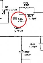
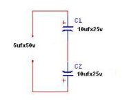
The Cyrus has symmetrical (+/-) supply rails, that means the cap should be bipolar electrolytic type to be able handling both polarity voltage swings. The common solution (in most similar topology amplifiers) is using standard (unipolar) electrolytics with the - pole connected to ground, but it can result in distortion at higher voltage levels. If in doubt use two 1000uF 6.3V unipolars in series with their -poles tied together in place of the single 470uf cap.
Attachments
Last edited:
The Cyrus has symmetrical (+/-) supply rails, that means the cap should be bipolar electrolytic type to be able handling both polarity voltage swings. The common solution (in most similar topology amplifiers) is using standard (unipolar) electrolytics with the - pole connected to ground, but it can result in distortion at higher voltage levels. If in doubt use two 1000uF 6.3V unipolars in series with their -poles tied together in place of the single 470uf cap.
Can you tell me where I could get a suitable replacement capacitor - I'd rather get a single one that fits rather than having to use two.
It will (should) show 0 (zero) Volts, because it is a symmetrical supply amp (no output capacitor, no DC voltage there), as mentioned before, that's why the cap needs to be bipolar.
No, it will show a low millivolts reading due to the small DC offset.
Aluminum Electrolytic Capacitors - Leaded | Mouser
Any of these should work if they fit. Check for Lead Spacing and size.
Any of these should work if they fit. Check for Lead Spacing and size.
Thanks - I'm building up an order now. I do have another issue with the LED circuit. There are two resistors - R119 and another resistor in D12. Is this original? This part of the circuit looks badly bodged and baked and I wanted to be sure that this was all correct. I know that D12 was removed but I wasn't sure if it was repalced with anything. Both resistors are 100R 1.6W. Is this correct? I read somewhere that the current passing through R119 can be quite high so is it worth fitting a higher rated resistor to help reduce heat?
I'm also looking for a good audio pot for the volume control as I think my unit was dropped and the wafers in the pot assembly were all cracked and no longer function. I tried on Omeg pot with a long axle but the volume is too loud too quickly and there is a discrepancy between the wafers - As I turn up, left turns up before right, and right drops before left when I'm turning it down.
As far as I was aware, the original was a linear. the code on the old one is 10K-B
B curve is linear as far as I know...
No, B is logarithmic. And B is also linear.
B means nothing for potentiometers, since it can be both. You have to measure the thing to be really sure.
No, B is logarithmic. And B is also linear.
B means nothing for potentiometers, since it can be both. You have to measure the thing to be really sure.
Ok - thought I originally bought another linear 10kB linear pot and that one appeared to work as normal with good volume control so I just thought this pot wasn't up to scratch.
How do I best measure it to know what it is? it mmight be possible to get a reading from one of the old pots as I think one is still intact from the set of the three...
Think about it - the resistance progression from one end of the pot to the wiper (the centre pin) is linear in one type and roughly logarithmic in the other. Linear implies that when the wiper is in the mid position, a resistance measurement from that pin (W) to either end (A or B in the diag.) will measure about the same at half the nominal resistance value.How do I best measure it to know what it is? it mmight be possible to get a reading from one of the old pots as I think one is still intact from the set of the three...
The log. pot however, will show quite different resistance at the mid position. Let's say it may read 90% or 10% of the nominal value, depending upon which of the end pins you measure to. This is all pretty simple and obvious once you realize what the terms mean by your measurement. If you are measuring in circuit, note that other resistances can affect the pot. operation and don't try this with power on since it's a DC test.

Just an update - I ordered Nichicon Muse caps that arrived today - replacing the rodensteins and all the other NP caps in the amp. My next task is to work on the pot. I measured it today and the initial reading of the pot is 8k on one wiper and 7k on the other. Seems to be quite a discrepancy...
Update
An update on my Cyrus project - I got round to looking at it agian and made n extension to the volume pot shaft and connected it all up and its all sounding good.
My only problem is with the LED. I uprated the two resistors to 2W in a bid to try and help with the heat - my thoughts were if it was higher rated then it wouldn't get so hot.
After about five minutes being on, the resistors start to smell quite unpleasant... maybe this would stop but I don't feel comfortable with them being so hot...
Is there a way I can drop the current running through the LED and resistors to a more sensible level or a way I can manage the heat?
- Status
- This old topic is closed. If you want to reopen this topic, contact a moderator using the "Report Post" button.
- Home
- Amplifiers
- Solid State
- Cyrus 2 - V7 Roedensteins...