wow that is absolutely brilliant I've gone from despondent to determined in the space of 2 minutes, cheers !Its getting toward the wrong end of the day for thisbut here is how I would proceed...
If you have a lower wattage bulb such as a 60W then lets use it but nothing to small. If not we stick with the 100W
The bulb tester is our main safety feature, and it will limit the overall power that the transformer can deliver on the secondary side.
Although the bulb shouldn't be bright (which indicates a problem somewhere) we still need to work with this to see what is going on.
If you haven't the correct the fuses for the secondary side then we can link them out as a temporary measure providing we are always using the bulb tester. The original fuses will probably be marked AT or T which denotes time delay or anti-surge. A little over 1A would be around the level of fault current the bulb would allow, the 3.15A wouldn't have blown.
We also need to go to the next level for forcing zero bias which is to apply a short across the bias transistor... this removes the whole preset and the transistor out of the equation. Shorting the cap across the transistor is perhaps an easier option.
Now we test again. If the bulb is still bright then you need to measure the following.
1/ The DC voltage on fuse 1 that has been replaced/linked.
2/ The DC voltage on fuse 2 that has been replaced/linked.
The above measured with respect to ground.
3/ The DC voltage across either of the 0.22 ohm for left channel.
4/ The DC voltage across either of the 0.22 ohm for right channel.
The voltage across the 0.22 ohm will tell us if that is where the fault current is flowing, and if it is, in which channel/s.
If anything is getting unduly hot in the amplifier section then switch off and terminate the test.
Fault finding is all about gathering evidence, that is what makes it so interesting
You can also do a quick resistance check (with the amp off course) between each metal tab of the output transistor and the metal chassis, just to make sure the insulation is OK and they are isolated correctly. You will get weird and wonderful readings due to interaction with all the circuitry, but none of the four should show a dead short to the metalwork.
There's no point second guessing at this stage. We methodically gather evidence now.
dead short from one output transistor to hearsink. hoping that's not just why it blew just now but the entire problem. nipping up to farnell in preston for 4 (8 !Fault finding is all about gathering evidence, that is what makes it so interesting
You can also do a quick resistance check (with the amp off course) between each metal tab of the output transistor and the metal chassis, just to make sure the insulation is OK and they are isolated correctly. You will get weird and wonderful readings due to interaction with all the circuitry, but none of the four should show a dead short to the metalwork.
There's no point second guessing at this stage. We methodically gather evidence now.
mje3055t and more bd139/BD140 and some low power trans , also hearsink thermal tape and more solder braid ....there was just thin thermal tape , that clearly has no integrity. farnell in preston didn't have thin thermal adhesive tape on a roll so i got 'akasa thermal double sided adhesive tape' as an 80x80mm sheet ''micro-fibreglass reinforced" "ideal for heatsinksThe middle leg and also the metal tab of the transistor is the collector. That should be isolated from the heatsink via a mica or silicon washer and also a plastic bush through the centre hole.
So which transistor and which leg reads dead short to the heatsink ?
got a handful of mje3055t's and new drivers for the other channel (out of stock the other day) so that's good. and will check for shorts before throwing the lever this timethere was just thin thermal tape , that clearly has no integrity. farnell in preston didn't have thin thermal adhesive tape on a roll so i got 'akasa thermal double sided adhesive tape' as an 80x80mm sheet ''micro-fibreglass reinforced" "ideal for heatsinks
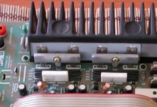
clamp with an aluminium thingy that connects/glues to a ? thermistor between the outputs.Just looking for pictures. Are your like this (first picture) and held with a clamp rather than each transistor screwed individually to the heatsink ?
I've removed the old tape and fitted fresh . reassembling now with fresh drivers , outputs and fuses and fingers xd !I prefer that method tbh.
Don't overtighten the clamp, tight but not that tight the transistors start cutting into the material behind.
Also, when you loosen the clamp and move the transistors forward, the short (if caused by this material) should disappear.
nothing went up in smoke this time at least. checking psu side voltages then might have to call it a day.
Don't overtighten the clamp, tight but not that tight the transistors start cutting into the material behind.
Also, when you loosen the clamp and move the transistors forward, the short (if caused by this material) should disappear.
voltages at the fuses are 28.5 and -29.8nothing went up in smoke this time at least. checking psu side voltages then might have to call it a day.
voltages at diodes D13 and D16 however are 28.5 and 29.8 also ! ??
vr1 measures -18.6 on the leg nearest the edge of the board.voltages at the fuses are 28.5 and -29.8
voltages at diodes D13 and D16 however are 28.5 and 29.8 also ! ??
vr2 measures 17.1 on the tab
That all sounds good so far. The voltage on one fuse should be positive and on the other negative. Same voltage on each end of the fuse of course
The -/+17 volt rails seem OK which are used for the preamp stages.
The next critical measurement is the DC offset which is voltage on the main amplifier output (the junction of the two 0.22 ohm resistors). Measure from ground to this point. Meter on DC volts.
This should be within 100 millivolts of zero.
clamp with an aluminium thingy that connects/glues to a ? thermistor between the outputs.
The 'thermistor' that was glued to the clamp (which will be Q39 ? the one the bias preset connects to) is used for thermal feedback and it is important it is in thermal contact with the metal. It needs to be a reliable fixing method that will stay put and not crack off.
Worry about the finer points of that when it is all basically working.
the centre point of the .22s to ground is 1.6v DC for both channelsThat all sounds good so far. The voltage on one fuse should be positive and on the other negative. Same voltage on each end of the fuse of course
The -/+17 volt rails seem OK which are used for the preamp stages.
The next critical measurement is the DC offset which is voltage on the main amplifier output (the junction of the two 0.22 ohm resistors). Measure from ground to this point. Meter on DC volts.
This should be within 100 millivolts of zero.
any idea what could be throwing the DC offset ?
29.5 on FS1
-30.5 on FS2
The manual says "if the voltage is too high, it can be reduced by increasing the value of R81 to the next preferred value of 180R. (from 130R)
"if the voltage is too low connect a resistor of value 220R across R81 using the solder pillars fitted to the pcb"
do you think they mean leave the 130R R81 in place and connect a 220R across it as well ? or remove the 130R from r81 then connect a 220R ?
I suppose what's curious is they don't say
"connect a 180R across the solder posts on the pcb" as they do for the voltage too low scenario.
DC offset now settled at 0.64vthe centre point of the .22s to ground is 1.6v DC for both channels
any idea what could be throwing the DC offset ?
29.5 on FS1
-30.5 on FS2
The manual says "if the voltage is too high, it can be reduced by increasing the value of R81 to the next preferred value of 180R. (from 130R)
"if the voltage is too low connect a resistor of value 220R across R81 using the solder pillars fitted to the pcb"
do you think they mean leave the 130R R81 in place and connect a 220R across it as well ? or remove the 130R from r81 then connect a 220R ?
I suppose what's curious is they don't say
"connect a 180R across the solder posts on the pcb" as they do for the voltage too low scenario.
DC offset and bias are two separate things...... so lets start again with these measurements. It is possible the chassis point isn't at a true 'zero' as far as measurements go. The fact both channels are identical seems to show a measurement problem rather than a fault at this stage 
Lets concentrate on checking the DC offset.
Meter on DC volts. This time connect the meter leads across the speaker terminals for each channel in turn. What do you get on both channels ? The manual says within 50 millivolts of zero. This is a non adjustable figure and the result is determined solely by the DC balance of the complete circuit... the bias preset has no effect on this.
thanks very much . is the fact that the rails don't measure the same why zero is shifted to one side?DC offset and bias are two separate things...... so lets start again with these measurements. It is possible the chassis point isn't at a true 'zero' as far as measurements go. The fact both channels are identical seems to show a measurement problem rather than a fault at this stage
Lets concentrate on checking the DC offset.
Meter on DC volts. This time connect the meter leads across the speaker terminals for each channel in turn. What do you get on both channels ? The manual says within 50 millivolts of zero. This is a non adjustable figure and the result is determined solely by the DC balance of the complete circuit... the bias preset has no effect on this.
between speaker posts measures 5mV
cheers !
- Home
- Amplifiers
- Solid State
- Cyrus 1 output transistor question. push-pull?