Kevin,
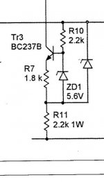
do you know the value of the other zener to the right?
Hopefully it's greater than 5,6V to make that circuit work sufficiently, because if equal to ZD1 the current through ZD1 will be very small and it means the zener voltage may be even up to 1 volt lower or so than the marked "5,6V" making this circuit a bit unpredictable of the theoretically calculated current and you have to meassure then, this is because Zener voltage vary a lot depending on the zener current.
Say we need a zener current of 1 mA, that means we have a voltage fall of 2,2 Volts over R10, meaning the other Zener diode should be at least5,6 + 2,2 = 7,8, rounding up to closest standard value 8,2 V.
I assume actually the other zener being of quite low value due to the power marking R11 being 1W, eg. it seem to have been choosen to work with "high" voltage.
With the other zener being 8,2 V the current alone through the zener would be approx 12 mA, which corresponds to around 330 mW in R11.
Cheers Michael
Isnt it possible to measure with circuit in operation?
Current passing a resistor is always Voltage/R
Constant current in this case is Voltage/1.8k
where Voltage is voltage over resistor
Zenerdiode voltage can also be measured
I guess you can not run your circuit.
Alternative then is to demount components and measure
or run them in test circuits
Current passing a resistor is always Voltage/R
Constant current in this case is Voltage/1.8k
where Voltage is voltage over resistor
Zenerdiode voltage can also be measured
I guess you can not run your circuit.
Alternative then is to demount components and measure
or run them in test circuits
Hi lineup,
Correct, the voltage across R7 is the value this will sink. That will be 5.6 V - about 0.6 V which gives you around 5 V across 1K8.
Hi Kevin,
10V is a good value, this tells us that the ZD1 current is close to 2 mA. Therefore the current through ZD1 is stable and the circuit will operate properly.
-Chris
- Status
- This old topic is closed. If you want to reopen this topic, contact a moderator using the "Report Post" button.
- Home
- Amplifiers
- Solid State
- Current supplied by CCS