This is not the case with VFAs with a differential pair for their input because the feedback network does not load the input device. Which is why the bandwidth of a VFA does not vary with the value of the feedback components.
Agreed.
I think I proved that, for a particular "CFA topology", it is possible to identify the known CFA properties using the VFA hij canonical model and methodology. For large closed loop gains, this particular topology acts as a standard VFA, while for low closed loop gains it transitions to the known CFA behaviour. But as Scott already mentioned, nobody would use a CFA at high closed loop gains, there is no advantage, no special properties, and a standard "VFA topology" (with differential pair input stage, etc...) would do a much better job, anyway. However, at low closed loop gains, the CFA properties are unique and impossible to reproduce with a "VFA topology".
I hope this will persuade you to also agree that this entire debate is semantic. Good night.
Last edited:
RIchard may be referring for example to the quad from ADI - very intriguing input structure. I guess it's still under patent, but I sure as hell would like to try that in a power amp - ditch the diode biasing and just go for a classic CFA buffer. Yum.
Which one? The best of the xDSL drivers have an extra VAS, a couple used a CFP output instead.
However, at low closed loop gains, the CFA properties are unique and impossible to reproduce with a "VFA topology".
And a good thing too, because that property that a so-called "CFA" possesses at low closed loop gains of reduced forward path gain and, therefore, reduced bandwidth, is simply undesirable in all respects.
This is because it needlessly reduces the loop gain that would otherwise be available if the voltage feedback divider did not affect the forward path gain of the amplifier, as is the case with VFAs which use a differential pair for their input stage.
However, a so-called "CFA" remains a VFA regardless of the variation of bandwidth with voltage feedback; it should never have been called a CFA.
Last edited:
What if the remaining forward gain has little non-linearities?
That is how does the linearity of a typical cfa input stage compare with that of an LTP, when taken in isolation?
Thanks
-Antonio
The typical cfa is superior for the same power drawn, however LTP topologies have much higher loop gains that together with feedback produce very linear circuits. The advantage of LTP is only at lower frequencies.
Youll note I said "same power" as it is possible to design a vfb (LTP)topology with near identical characteristics but at maybe 5 to 8 times higher tail current and heavy degeneration. Thats CFAs other important characteristic, low power can yield high bandwith and slewrate.
The typical cfa is superior for the same power drawn, however LTP topologies have much higher loop gains that together with feedback produce very linear circuits. The advantage of LTP is only at lower frequencies.
It's possible to use advanced type of compensation, TMC is one of them, and have wide open loop bandwidth with LTP too.
It's possible to use advanced type of compensation, TMC is one of them, and have wide open loop bandwidth with LTP too.
Not quite like the cfb topology and at a cost of power and complexity (usually noise too).
The second part of my post "Youll note I said "same power" as it is possible to design a vfb (LTP)topology with near identical characteristics but at maybe 5 to 8 times higher tail current and heavy degeneration. Thats CFAs other important characteristic, low power can yield high bandwith and slewrate."
Manso,
Thanks, can you take it a step further, if just considering cfa and vfa input stages with the same high impedance load, no further distortion mechanisms, and the same idle current through the input transistors (and staying reasonably within this idle current) is there an advantage to the cfa?
Thanks
-Antonio
Page 12 of Walt Kester app note - the 'quad core' VFB gm stage. No current source as far as I can tell, should be very fast.
That's just the "H" bridge input, think buffering the - input of a CFA then is is a VFA.

However, a so-called "CFA" remains a VFA regardless of the variation of bandwidth with voltage feedback; it should never have been called a CFA.
Except of course if no current flows out the - input there is no feedback. This current also contains the distortion of the capacitive non-linearity at the gain node. This current is manifest as a voltage across across Rf, looking at it another way is only an artifice that adds confusion when getting down to fine scale problems.
Last edited:
Manso,
Thanks, can you take it a step further, if just considering cfa and vfa input stages with the same high impedance load, no further distortion mechanisms, and the same idle current through the input transistors (and staying reasonably within this idle current) is there an advantage to the cfa?
Thanks
-Antonio
The answer is yes. There is a reference paper by Smith where he demonstrates this but google doesnt seem to find it any longer ??
This is because it needlessly reduces the loop gain that would otherwise be available if the voltage feedback divider did not affect the forward path gain of the amplifier, as is the case with VFAs which use a differential pair for their input stage.
However, a so-called "CFA" remains a VFA regardless of the variation of bandwidth with voltage feedback; it should never have been called a CFA.
Disagree on first point, the minimum Rf is the smallest gm at which the CFA is stable. A VFA would require the same reduction in gm to be stable.
Take the case of a CFA 250uA in the input stage and 200Mhz BW at G = 1 with a 1K Rf. A VFA at 10mS of gm and the SAME comp cap IS NOT UNITY GAIN STABLE (most likely, would have to be 2GHz). The 1K has to be added as degeneration, and we are back on equal ground.
Last edited:
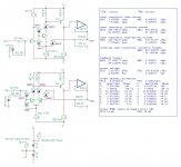
This is very a basic comparison between a so-called CFA in a simplified form and a VFA.
It shows that input transistors T11 and T21 work at AC and DC with identical values. Their output current is determined by their Vbe
It's quite difficult to see where a current is fed back.
It shows that input transistors T11 and T21 work at AC and DC with identical values. Their output current is determined by their Vbe
It's quite difficult to see where a current is fed back.
Attachments
What if the remaining forward gain has little non-linearities?
That is how does the linearity of a typical cfa input stage compare with that of an LTP, when taken in isolation?
Thanks
-Antonio
A properly balanced LTP generates far less even order distortion than a so-called "CFA" input stage.
Notice that typically so-called "CFAs" are single gain stage arrangements: merely a pair of complementary common-emitter amplifiers with each acting as the collector load for the other and current mirrors used for level shifting.
Therefore, the amount of forward path gain, and, thus, loopgain, generated by the "CFA" is far less than that generated by traditional VFAs with an LTP first stage.
Last edited:
.....is there an advantage to the cfa?
There are no advantages in audio applications of so-called "CFAs".
- Status
- This old topic is closed. If you want to reopen this topic, contact a moderator using the "Report Post" button.
- Home
- Amplifiers
- Solid State
- Current feedback - Voltage feedback, how do I see the difference?