The word current says enough, current feedback is on low impedance nodes and voltage feedback is high impedance nodes.
Current feedback, very low TIM, very high slew rate, out, offset unstable so need a servo,
stable, easy frequentie correction, a lot less fase error then voltage feedback, amp can be extreem fast because of indepencedy of bandwith, low open loop design possible even a must (low feedback amps, better offset stability?), and these are all for the good, voltage feedback has a lot problems like bandwith limiting, unstable,high TIM when bad designed, still much more TIM in good design then current bad design, high open loop needed for fase error free operation.
You need more good things of current feedback, for me it sounds the best, fast high slew rate, stable except the offset this do walk when not a servo because of sensitivity for heat in parts current loop....?
Attachments
Ok. Lets see if we can align then.
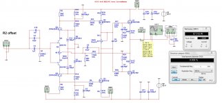
If they are voltage feedback circuits, can we use the simplifying assumption that we could vary the value of the feedback network significantly, but keeping the ratio the same, without materially changing the closed loop performance?
If they are voltage feedback circuits, can we use the simplifying assumption that we could vary the value of the feedback network significantly, but keeping the ratio the same, without materially changing the closed loop performance?
Last edited:
The input node is what make voltage or current feedback, low emitter follower node is current, and base input is voltage (high impedance) you can with current or voltage change things without impact the performance, frequency correction is more needed with voltage feedback, and TIM is much higher, that is why current feedback has so much better sound and only a minus point is the offset drift, use a servo.
There is no much other things to say about it, I use hybrides without feedback.
There is no much other things to say about it, I use hybrides without feedback.
The word current says enough, current feedback is on low impedance nodes and voltage feedback is high impedance nodes.
Yes, that's quite understandably, and has an intuitive ring to it. It's more subtle than that though; if you have say 1V feedback signal at an emitter node with a 10 ohms impedance, no one should expect a 100mA current into that node - it's probably closer to a few millionth of that. The current into that node is more a function of the loop gain than of the node impedance.
The terminology confusion arises because people who learned about feedback when studying electronics or feedback and control theory learned that if you feedback a signal depending on the output voltage, you'd call that voltage feedback. Feedback a signal that depends on the output current that would be current feedback. Just as your convention, this is also quite logical: voltage feedback makes the amp into a voltage source, current feedback makes the amp into a current source.
So two systems, both logical, diametrically different. Scope for confusion!
jan
I'am totally in line with KEE52,
I look at it this way. what is that drives the circuit where you inject til feedback. is it current or is it voltage. if you go in through the base, like on a LTP, then its voltage feedback, if you inject below the device at a low impedance node then it's current feedback.
I look at it this way. what is that drives the circuit where you inject til feedback. is it current or is it voltage. if you go in through the base, like on a LTP, then its voltage feedback, if you inject below the device at a low impedance node then it's current feedback.
I'am totally in line with KEE52,
I look at it this way. what is that drives the circuit where you inject til feedback. is it current or is it voltage. if you go in through the base, like on a LTP, then its voltage feedback, if you inject below the device at a low impedance node then it's current feedback.
Hey, not a problem! In this post-fact society, anybody's opinion is as good as anybody else's opinion or fact.
I just wanted to mention that it is taught differently.
jan
A CFB input stage with proper dimensioned RE's is far more linear.
Cheers,
E.
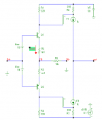
Edmond do you mean resistors in the emitters of the feedback node?
I thought that was current in/ current out? How does that improve linearity.
Edit Ohh I think I get it. That device is really a differernce amp between it's emitter and base, right?
jan
Last edited:
Let's make it clear -- current feedback amplifier or opamp, since in closed-loop, current is fed back (set by the value of Rf) from the low impedance output to the low impedance inverting input -- that is the CF opamp operates with voltage-sampling, current-feedback. And, gain is set by the R from the inverting input (emitter) to ground.
Thx-RNMarsh
Thx-RNMarsh
Correct me if am wrong, but I reckon where you're going wrong is assuming "these new fangled CFA thingies" are current feedback amplifiers; they are not, by any strech of the imagination; they are, in fact, voltage feedback amplifiers because the signal fed into the emitter(s) of the input stage is a voltage.
You should read the paper " HIGH SPEED OPERATIONAL AMPLIFIERS " by Walt Kester of Analog devices. The naming of the CFB topology has nothing to do with whether the feedback is a voltage or a current, it is the result of the feedback action which is the reason for the naming.
I have posted this before but seems no one read it. Here is the link, see page 14, first paragraph. This is what I was taught in university so there s no mistaking it with feedback theory.
http://www.analog.com/static/imported-files/seminars_webcasts/36692482463115527495427664003sect1.pdf
This is the same as I just earlier put up from AD's archives (see Fig 1-110).
Look at Fig 1.15. The AD8011 topology (1995) was from earlier work by others before it was put into IC package. You will find the topology origins in the article that I did in Vol 3 of Linear Audio.
But to make a long story short.... I did it and published it in TAA back in 1980... pre Elantec. My original work was done in the late 1970's. It was done as a line stage and also similar idea was published for a MC pre-preamp. The MC pre-pre used complimentary push-pull common-base input with cartridge as emitter/gain resistor. Ckt used gnfb to input to further reduce input Z and load the MC cartridge to lower its distortion right at the source.
Thx-RNMarsh
Last edited:
if helps:
Download current-feedback.pdf from Sendspace.com - send big files the easy way
CFB audio amp by Analog Device
Download current-feedback.pdf from Sendspace.com - send big files the easy way
CFB audio amp by Analog Device
Edmond do you mean resistors in the emitters of the feedback node?
I thought that was current in/ current out? How does that improve linearity.
Edit Ohh I think I get it. That device is really a differernce amp between it's emitter and base, right?
jan
Hi Jan,
See picture.
>How does that improve linearity?
Same principle as with class B output stages.
Re1 + internal emitter bulk resistance should equal to 26mV/Ie (at room temperature, at least).
Cheers,
E.
Attachments
This is the same as I just earlier put up from AD's archives (see Fig 1-110).
Look at Fig 1.15. The AD8011 topology (1995) was from earlier work by others before it was put into IC package. You will find the topology origins in the article that I did in Vol 3 of Linear Audio.
But to make a long story short.... I did it and published it in TAA back in 1980... pre Elantec. My original work was done in the late 1970's. It was done as a line stage and also similar idea was published for a MC pre-preamp. The MC pre-pre used complimentary push-pull common-base input with cartridge as emitter/gain resistor. Ckt used gnfb to input to further reduce input Z and load the MC cartridge to lower its distortion right at the source.
Thx-RNMarsh
View attachment 338430

Look familiar?
Thx-RNMarsh

Last edited:
I did a search on this thread for tanh. Nothing!
Amazing that nobody mentioned it with regard to the LTP of a VFB input stage thus far. A CFB input stage with proper dimensioned RE's is far more linear.
Cheers,
E.
Edmond
I could have mentioned both tanh and multi-tanh, but as I see it Mikeks is not interested in any technical discussion, his agenda is to try to prove that the CFA is useless for audio and is a compromised version of the VFA (which is not right).
BTW: Jan (and Mikeks) is right about the definition of "current-feedback" in control theory. I remember it from when I studied control theory back in the seventies.
BTW2: There are other IPS than LTP in VFA's, my preferred VFA IPS is H-bridge, best of both worlds.
Stein
ADI is a great resource.
Read:
MT-034
MT-051
MT-057
MT-059
Are all these papers wrong?
I also recommend reading: Evolution of high-speed operational amplifier architectures
Stein
Read:
MT-034
MT-051
MT-057
MT-059
Are all these papers wrong?
I also recommend reading: Evolution of high-speed operational amplifier architectures
Stein
Attachments
I remember those articles! I learned a lot from them at the time Richard!
jan
Hi Jan,
See picture.
>How does that improve linearity?
Same principle as with class B output stages.
Re1 + internal emitter bulk resistance should equal to 26mV/Ie (at room temperature, at least).
Cheers,
E.
OK yes got you.
thanks, jan
Just for the record -- Internet is forever -
Its fun here to see how far my little topology/concept has been taken. And, how good they have become for audio as well.
According to the literature, it was primarily the PNP/NPN process technology for IC manufacturing that held back its adaption for IC use. Until there could be truely good complimentary pairs made, it had to wait.
Wish we could get those compliments as descrete pairs.
Enjoy ! -- Richard Marsh
I remember those articles! I learned a lot from them at the time Richard!
jan
Its fun here to see how far my little topology/concept has been taken. And, how good they have become for audio as well.
According to the literature, it was primarily the PNP/NPN process technology for IC manufacturing that held back its adaption for IC use. Until there could be truely good complimentary pairs made, it had to wait.
Wish we could get those compliments as descrete pairs.
Enjoy ! -- Richard Marsh
Last edited:
- Status
- This old topic is closed. If you want to reopen this topic, contact a moderator using the "Report Post" button.
- Home
- Amplifiers
- Solid State
- Current feedback - Voltage feedback, how do I see the difference?