mikeks said:
Well...if i buffered a simple LTP input stage that wouldn't make it a so-called CFB would it??
Depends on how you connect it. If you ground one input and
use the buffered output as inverting input and then sense
the buffer current, then yes. I can't see why there is so much
discussion about this really. I think the app notes I linked to
and that both I and others have linked to many times before
are very clear about this.
mikeks said:Christer.....LTP not used for 'current' feedback.....There is no such thing as 'current' feedback in the sense described by the app. notes you've presented....
I think i'll retire from this thread...
I am sorry that AD, BB, TI, Intersil, Elantec and others didn't
clear it with you before they decideded to overload the
term current feedback with a new meaning. You can't behave
like an ostrich. The term is there, whether you like it or not.
In my profession it is normal having to deal with multiple and
even conflicting terminology on an almost daily basis. I would
think that is the case in many/most other professions as
well. It seems only EEs think they are an exception here.
mikeks said:Nothing to do with 'terminology' per se....
This is a whole new level of absurdity.....equivalent to calling a lorry a four wheeled motorcycle...
Any such claim is based on certain assumptions which you
happen to hold, but which are not universally true. I am not
saying the term is fully satisfactory, but the phenomenon is
there and we have to call it something. Sometimes we have
to accept a less than satisfactory terminology just to be able
to talk about something at all. Besides, I don't think it is
entirely inappropriate. The current flowing in the negative
input is roughly proportional to the error in the output signal.
Christer said:
Any such claim is based on certain assumptions which you
happen to hold, but which are not universally true.
No assumptions Christer.....facts....100% facts...independently established by no less than Baxandal, Cherry...etc...
Indeed, these facts are to be found in almost any good book...worthy of the name...
Christer said:
I am not
saying the term is fully satisfactory, but the phenomenon is
there and we have to call it something.
The term....as used here....is entirely misleading, incorrect, and as used, entirely without merit.....
The 'phenomenon' doesn't need calling 'something'...it's called voltage feedback....Period.
Christer said:
The current flowing in the negative
input is roughly proportional to the error in the output signal.
No...
millwood said:aren't you guys really into this thing or what?
here is an amp. Tell me what it is an VFB or CFB.
Since there isn't a feedback network, and the type of feedback depends on how you configure the feedback, you can't tell.
Jan Didden
Christer said:
Many discrete designs that seem intended as CFB amps have
to high negative-input impedance wrt. the feedback network
to be really considered CFB amps. Maybe they aren't intended
to be CFB amps after all? Yet, I think the impedance is also too low
to think of them as VFB amps. They actually land somewhere in
a greyzone inbetween. However, If we changed values so
the negative-input impedance were much lower than 10 Ohms,
and maybe also increased the impedance of the feedback
network, then it would be a different case, do you agree?
Not really, Christer. My main pojnt has always been (Iand I know I am in good company here) that the driving signal in these cases is voltage: the voltage that results from subtracting the input voltage from the feedback voltage which gives the driving Vbe, in this case at the second stage. The first stage really is just a buffer/emitter follower which doesn't count for this discussion.
The fact that the feedback network and inverting input impedances are so unusual merely nicely illustrate the point that they really are not the decisive factor.
Jan Didden
janneman said:Since there isn't a feedback network, and the type of feedback depends on how you configure the feedback, you can't tell.
Jan Didden
I am sorry but it is the wrong answer.
Anyone else want to try? You need to also explain your answer as well.
millwood said:
I am sorry but it is the wrong answer.
Anyone else want to try? You need to also explain your answer as well.
Aha! Thanks for the clarification.
You realise of course that I can make your amp in any feedback configuration I (or you) want, just by arranging the feedback network that is conspiciously missing in your diagram.
Jan Didden
millwood said:
I am sorry but it is the wrong answer.
Anyone else want to try? You need to also explain your answer as well.
It's VFB, because the inverting input is high impedance, and the impedance of the feedback network will only change the amplifier dynamics through its interaction with parasitic capacitance.
But I'd love to see a CFB amp with a diffpair input stage.
-- mirlo
mikeks said:
correct...the feedback network is deliberately selected to load down the first stage....i.e. reduce first stage gain as closed loop gain is reduced, (and conversely).....so that bandwidth appears constant....
the low feedbak network resistor values mean that the input stage runs in class-AB, which explains why you can have a much higher slew rate than the nominal quiescent current suggests....
In a CFB amp, the lower the feedback impedance, the faster the amplifier is.
The current in the inverting input is the error signal divided by the feedback impedance.
This current is integrated in the amplifying stage.
In a VFB amp, this current is also proportional to the error signal, but the constant of proportionality is the input stage transconductance, nothing to do with the feedback impedance.
mirlo said:
It's VFB, because the inverting input is high impedance, and the impedance of the feedback network will only change the amplifier dynamics through its interaction with parasitic capacitance.
But I'd love to see a CFB amp with a diffpair input stage.
-- mirlo
Post 162, fig b and d, just replace the amp block with Millwoods' amp.
Jan Didden
janneman said:
Aha! Thanks for the clarification.
You realise of course that I can make your amp in any feedback configuration I (or you) want, just by arranging the feedback network that is conspiciously missing in your diagram.
Jan Didden
no you cannot.
just pay very close attention to how the ltp works. It is a ltp, but it isn't your typical ltp either,
") . try to vary the signal and see what happens to the ltp's output.
. try to vary the signal and see what happens to the ltp's output.
millwood said:
no you cannot.
just pay very close attention to how the ltp works. It is a ltp, but it isn't your typical ltp either,
The LTP has nothing to do with it. I couldn't care less whether is was a mechanically driven organ. Feedback type is all about how you combine input signal and feedback signal to develop the real driving signal to the amp. See post 162 and 193.
Jan Didden
mikeks said:
PMA said:LTP based input stage creates so called VFB opamp and emitter input singleton based input stage (and preferably symmetrical in polarity) creates so called CFB opamp - it is very simple.
Correct....in all respects.....Thanks Pavel!!!...
So I was right then...!
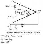
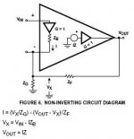
Attached two pictures Mr "Whats-on" can go and figure out!
Psst! ..a tip, they are scarying similar so look carefully!
Would also like to borrow a sentence from Mr Pass: The gain stage doesn't know in which mode it does work in.
Cheers!
Attachments
mikeks said:
The 'phenomenon' doesn't need calling 'something'...it's called voltage feedback....Period.
It exists, hence it is useful to have a name for it. It is quite a
difference if an amp input has infinite impedance or zero
impedance, hence we need to distinguish the cases.
No...
Yes
- Status
- This old topic is closed. If you want to reopen this topic, contact a moderator using the "Report Post" button.
- Home
- Amplifiers
- Solid State
- Current feedback - Voltage feedback, how do I see the difference?