Yassou, my Greek friend!.
is this what you are looking for?
regards
Prasi
here is eliminating 3rd jumper and possibility to couple T 1/ T2.
Also gnd lift res, if required can be put.
reg
Prasi
Attachments
Prasi!Yassou, my Greek friend!.
is this what you are looking for?
regards
Prasi
Yassou Prasi!Really fast!!!!
")
Thanks my friend
Just an option....moving the +/- power terminals close together with the GND terminal if possible.
Attachments
Last edited:
Prasi!
Yassou Prasi!Really fast!!!!
Thanks my friend
Just an option....moving the +/- power terminals close together with the GND terminal if possible.
I can do it, but would you mind it if the o/p devices are some what submerged under the pcb? like the 'quasi complementary amp by AKSA/Ranchu32?
that would call for separate ground connection for i/p section like the Cubie-3? would you be comfortable with that?
reg
Prasi
Last edited:
Let's wait Juma's opinion,guides.
ok,
Hi Juma,
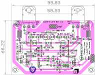
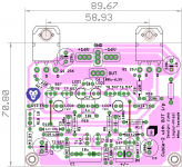
here is high contrast image as you prefer it. schematic with component names in post #160. PCB image as viewed from component side.
reg
Prasi
Attachments
Last edited:
Looks all right - watch the details: R16 in layout (R20 in sch., post #145) goes to signal GND not to power GND...
Thank you Juma, corrected in attached layout
.To thimios,
are you suggesting something like the attached?
reg
Prasi
Attachments
Last edited:
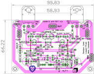
Yes,but now C2,C3 attached at the signal gnd. Schematic say POWER GNDThank you Juma, corrected in attached layout
To thimios,
are you suggesting something like the attached?
reg
Prasi
Yes,but now C2,C3 attached at the signal gnd. Schematic say POWER GND
No, C2/C3 (C4/C5 in Juma sch) are indeed attached to signal ground. Juma's sch shows only the signal ground.
Ok got itNo, C2/C3 (C4/C5 in Juma sch) are indeed attached to signal ground. Juma's sch shows only the signal ground.
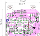
post168.
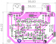
You now have the V+, V- and PG all grouped together to minimise EMI from the power lines. This is much better for reducing interference effects.
Add in HF supply rail decoupling where the PG is next to V+ and V-.
What are C2 and C3 doing? They appear to be connected to the Signal Return.
The unlabelled resistor between PG and Signal Return (-IN) allows a reference voltage between zero volts and input.
This resistor may have to pass Fault Current if the Source equipment becomes faulty and has no route (classII) to blow the mains fuse.
This resistor needs to be protected from failing until that remotely located mains fuse blows. Add in a pair of inverse parallel diodes across the resistor.
Last edited:
post168.
You now have the V+, V- and PG all grouped together to minimise EMI from the power lines. This is much better for reducing interference effects.
Add in HF supply rail decoupling where the PG is next to V+ and V-.
What are C2 and C3 doing? They appear to be connected to the Signal Return.
The unlabelled resistor between PG and Signal Return (-IN) allows a reference voltage between zero volts and input.
This resistor may have to pass Fault Current if the Source equipment becomes faulty and has no route (classII) to blow the mains fuse.
This resistor needs to be protected from failing until that remotely located mains fuse blows. Add in a pair of inverse parallel diodes across the resistor.
C2 C3 part of feedback network?
post # 1 is original JFET version of Cubie 2 amp.
Someone requested BJT i/p of Cubie-2 and Juma posted here..post #145.
http://www.diyaudio.com/forums/pass-labs/271543-cubie2-15.html#post4537151
I did my layout of the same and my sch (which is same as Juma BJT but different part numbers) is posted here. post no. 160
http://www.diyaudio.com/forums/pass-labs/271543-cubie2-16.html#post5116401
Attachments
- Home
- Amplifiers
- Pass Labs
- Cubie2