Juma, it doesn't seem to be a power supply problem. I mean, when a turn on the PS, offset voltage is just a few mV and going near zero, while temperature is going to a constant state. But, when I turn on the source, it's the point where this behavior happens.
Anyway, I can check this when I finally construct the amplifier's actual PS. For now, I'll be on the safe side, connecting the loudspeaker after all has set-up (and checking the voltage in the output terminals).
For now, I have started assembling the second (no feedback) channel.
Have a nice weekend,
Vagelis
I'm back here to report my findings after building, testing and listening to the no-feedback channel.
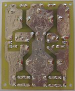
First of all, let me cite my trouble with it, as I was having a hard time for several days, trying to figure out why the amp was not working. In particular, there was no current flowing through the input and current mirror string. After much iteration, I found out that this was due to a very tiny gap between D2 and R14. This was caused from a tiny hair trapped between the photosensitive coated copper clad and the film. The fact was that, as I remembered afterwards, I had noticed that when I made the PCB, but I forgot to fix it. It was so tiny that it was not visible with a naked and I had to use a multimeter to trace down this discontinuity.
So, being happy that I managed to get it working, I adjusted and tested it on the bench, just to find out that the gain was too low. Playing around with the values of Ra and Rb (refer to post #225), I found out that the values of those two resistors should be reversed in order to get a gain of ca. 20 dB. Later on, reading again the text in post #1, I noticed that Juma says that Ra should be 1K, so, probably it was a mistake from being in a hurry .
After having ensured that everything is working right, it was time for the listening test. I must say that it didn't take too long to make my judgement. The superiority of the 0FB version was hands down clear in relation to the FB version. In particular, bass is deeper yet absolutely controlled, instrument separation is excellent, voices are precise and warm without being unnatural, highs are crystal clear and transparent, while the speed of the amp is exquisite.
Of course, here I have to mention that my loudspeakers are 2-way horn loaded (namely, Tune Audio's Marvel), which benefit from a high impedance (or, low damping factor) amplifier. That's why I wanted to try the 0FB version, since, from my experience, my speakers always sounded best with zero feedback amplifiers.
My final verdict is the following: If listening to the FB of Cubie2 version was a big surprise, listening to the 0FB version of this amp was a great revelation! So, no doubt, this little amp is going to find its permanent place in my system.
My only regret is that I didn't build Cubie2 earlier. Anyway, thanks to the coronavirus moving restrictions, this was a great opportunity to get some ample free time to get my hands down to projects I had left aside for some time now.
Saying this, I must express my greatest THANK YOU to Juma, for sharing this wonderful design.
Well, my task for the next days will be to make the PCBs for the cap multipliers, build the power supply (so far, all my testing was done with my lab PS) and put everything in a case.
Greetings,
Vagelis
Vageli, levendi mou! [emoji16]
that was some fight... but you won it in the end [emoji106][emoji1]
Na eisai kala!
Juma,
Esy na eisai kala, that you designed such a great sounding amplifier!
I'm really excited after my morning listening session and I'm really eager to finish it and sit down and enjoy in its full potential (remember that, so far, I was listening a la Samuma-san - i.e., in mono, and powered from a lab PS).
I hope that, by the end of this week, I will be able to finish it and post some pictures.
Regards,
Vagelis
Well, my journey, with Cubie2, finally, reached its end. After much study, trials, frustration and hours of labor, I am proud to claim that I have built the finest amplifier I ever connected to my speakers. The amp is finished a couple of weeks ago, but I wanted to give it an extensive testing (both laboratory and listening) before closing the case and presenting my findings her.
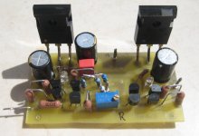
So, as I wrote previously (although in a semi-final state), I'm completely surprised from the final result. The sound is amazingly fantastic: extremely analytical without being clinical, voices are natural and warm without any sign of sibilance, instruments separation is exemplary, while bass is deep and firm. In all, I'm deeply satisfied from my new amp and I'm seeking for free time to sit down and enjoy it.
Frequency response is -0.1 dB at 20 Hz and +0.2 dB at 20 kHz. Initially, gain was a little bit high at 22 dB (very limited range from the volume control of my preamp), so I had to reduce the value of Rb (zero feedback design - refer to schematic in post #225) from 150R to 120R to bring the gain to exactly 20 dB. With +/- 16.5 V supply, power output (at the beginning of clipping) is 8 W (on a 8 Ohm load). Bias current is set to 0.85 A (since I have plenty of heatsinking and temperature rise is minimal).
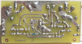
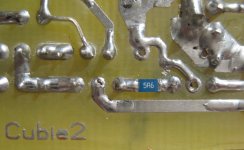
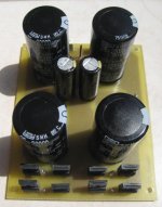
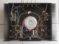
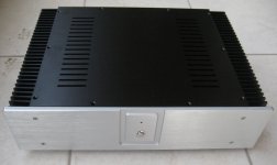
Below, I present a couple of pictures. On the PCB picture, please notice the 5R6 SMD resistor I have put on the source of 2SJ74. I made this, following the suggestion found elsewhere in this forum, in order to equalize the Yfs of J74 to K170 (since these are not truly complementary JFETs).
Juma, I would like to thank you once again, not only for providing such a beautiful design, but also, for all the help you gave to me through this journey. And, whenever you come to Athens again, I invite you to come to my place to listen your great amplifier on a great loudspeaker.
So, as I wrote previously (although in a semi-final state), I'm completely surprised from the final result. The sound is amazingly fantastic: extremely analytical without being clinical, voices are natural and warm without any sign of sibilance, instruments separation is exemplary, while bass is deep and firm. In all, I'm deeply satisfied from my new amp and I'm seeking for free time to sit down and enjoy it.
Frequency response is -0.1 dB at 20 Hz and +0.2 dB at 20 kHz. Initially, gain was a little bit high at 22 dB (very limited range from the volume control of my preamp), so I had to reduce the value of Rb (zero feedback design - refer to schematic in post #225) from 150R to 120R to bring the gain to exactly 20 dB. With +/- 16.5 V supply, power output (at the beginning of clipping) is 8 W (on a 8 Ohm load). Bias current is set to 0.85 A (since I have plenty of heatsinking and temperature rise is minimal).
Below, I present a couple of pictures. On the PCB picture, please notice the 5R6 SMD resistor I have put on the source of 2SJ74. I made this, following the suggestion found elsewhere in this forum, in order to equalize the Yfs of J74 to K170 (since these are not truly complementary JFETs).
Juma, I would like to thank you once again, not only for providing such a beautiful design, but also, for all the help you gave to me through this journey. And, whenever you come to Athens again, I invite you to come to my place to listen your great amplifier on a great loudspeaker.
Attachments

")
I can only comfirm, it is a great amp! For me it plays better than some popular amps out here... and my construction is simple with the powersupply shared by both channels (I see you have a separate supply for each amp)...
Can you point me were to find more info about the little resistor you talk about? I don't believe the resistor itself does anything in our case because of P1 in the schematic... How did you select / chose your Jfets? I mean, what are their Idds?
Can you point me were to find more info about the little resistor you talk about? I don't believe the resistor itself does anything in our case because of P1 in the schematic... How did you select / chose your Jfets? I mean, what are their Idds?
Last edited:
I can only confirm, it is a great amp! For me it plays better than some popular amps out here... and my construction is simple with the power supply shared by both channels (I see you have a separate supply for each amp)...
Yes, the power supply is sort of "dual mono". Generally, I prefer to separate power supplies for each channel, as the PS is part of the signal path itself. So, in my construction, the two power supplies only share the primary winding of the transformer.
Can you point me were to find more info about the little resistor you talk about? I don't believe the resistor itself does anything in our case because of P1 in the schematic... How did you select / chose your Jfets? I mean, what are their Idds?
I have found this information somewhere in the F5 thread (a very long thread) and somewhere in the following F5 headamp thread:
F5 Headamp ?
The idea of this is to degenerate the 2SJ74 in order to match its transconductance to that of the 2SK170. It's very easy to get a pair of matched Idss and measure the Yfs at a certain point. You will find out that there is a substantial discrepancy. Of course, you could use whatever you have in hand, but with a matched Yfs pair the 2nd order harmonic distortion is reduced.
As a rule of thumb, you chose a 2SJ74 with an Idss approximately 20% higher than that of the 2SK170 and you add a 5 Ohm degeneration resistor on the source of J74. And that's not a joke, because I have checked it myself. The K170 I used have an Idss of ca. 8.5 mA and the J74s are ca. 10 mA.
Talked about here also.
https://www.diyaudio.com/forums/pass-labs/121228-f5-power-amplifier-1008.html#post2445171
https://www.diyaudio.com/forums/pass-labs/121228-f5-power-amplifier-1008.html#post2445171
- Home
- Amplifiers
- Pass Labs
- Cubie2