Hi,
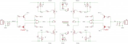
Just in case someone wants to use the BL type Jfet I have modified Juma's schematics based on his recommendations given to Marsupialx. There was also some minor modifications along this thread so I modified the schematic a little more. I have also gather here the 200VA power supply schematic for the Cap Multiplier provided by Juma in this thread.
Hope this helps someone.
Maybe Juma should bless the mods before anyone goes ahead..
p.s. Very nice and cool amp Mursupialx, congrats !!
BR,
Eric
R20 and R21 are now different. Is this to compensate for the slightly different characteristics of the p and n Lateral Mosfets? Sorry if this is dumb or obvious.
Last edited:
F4 won't help you there. F4 is a unity gain power buffer so it can only boost current delivery and Cubie is not short in supply there. What you need is more voltage times more current - the power delivered into the speakers is a product of current and voltage (P = V * I ) .
Cubie swings about 13V_peak at the output and at 4 Ohms it takes only 3.25A_peak into the load (and Cubie can supply twice that much).
What you actually want is a 100W Cubie. It means +/-50V rails, cascoded input JFETs, more paralleled MOSFETs in the output stage, maybe even some kind of follower stage betweeen input and output - in short Cubie Turbo, a whole new amp...
What's easily achievable - raising the PS voltage to +/-25V (400 VA transformer) and doubling the outputs in order to roughly double the power into 4 Ohms which, translated to SPL, means only +3dB per channel...

R20 and R21 are now different. Is this to compensate for the slightly different characteristics of the p and n Lateral Mosfets? Sorry if this is dumb or obvious.
There is no dumb question, you are perfectly right !
Hi Juma,
I have an F5 with Toshiba outputs. How does the sound compare? I'm looking build a cubie. Thanks.
Leo
I have an F5 with Toshiba outputs. How does the sound compare? I'm looking build a cubie. Thanks.
Leo
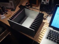
Since it's been decided that a small LU1014 based circlotron will be built and I need a 4 secondary transformer for that project, Cubie got a whole new PSU - a Sedlbauer 200VA potted toroid (2 x 15V secondaries) followed by a IRFP044N based cap. multiplier. It's on since yesterday and the change is not big, although noticeable - the presentations is a bit more cleaner and more defined (noticeable in big orchestral recordings) with a same gentle overall signature. So, it can be considered as an upgrade.
Here is the sch. and a couple of pics (big 0R1 ceramic resistors in the negative power rails are there just to check the bias current - they were removed after the measurement):
Hi ljfont,
subjectively, I prefer k1058/j162 over k1530/j201 in this circuit (+/-16V, GR grade JFETs). Toshiba's MOSFETs require more than 1A in order to sound good here. k1058/j162 have much better thermal behavior too.
If you intend to keep the same power supply voltage, JFETs, output stage Id, and just change the output devices, I think it's not worth the effort - keep the Toshibas in.
Main idea behind Cubie is to use GR grade JFETs in a great 10W amp and if you want to upgrade standard F5, the k2013/j313 will improve it significantly:
http://www.diyaudio.com/forums/pass-labs/168040-f5-2sk2013-2sj313.html
Thanks Juma,
I will keep my F5 with k1530/j201 intact as is. I've had it for 4 years and still going strong.
I'm going to build a cubie low power amp for a near field monitoring setup.
I have only "BL" types and will adjust resistors as mentioned previously in this thread. (Post #156) I am planning to use 12VAC without the cap multipliers as I have a smaller case than yours, and don't' want extra heat from the multiplier circuit.
Each heatsink is (21cm x 12cm and 5cm fins (8"x 4.75" and 2" fins).
What are your thoughts on the sound quality if I used the "BL" types and no cap multiplier. Do you think that having the cap multiplier will sound better?
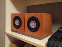
My speakers will be Mark Audio Alpair 6p used as small mixcubes.
I will keep my F5 with k1530/j201 intact as is. I've had it for 4 years and still going strong.
I'm going to build a cubie low power amp for a near field monitoring setup.
I have only "BL" types and will adjust resistors as mentioned previously in this thread. (Post #156) I am planning to use 12VAC without the cap multipliers as I have a smaller case than yours, and don't' want extra heat from the multiplier circuit.
Each heatsink is (21cm x 12cm and 5cm fins (8"x 4.75" and 2" fins).
What are your thoughts on the sound quality if I used the "BL" types and no cap multiplier. Do you think that having the cap multiplier will sound better?
My speakers will be Mark Audio Alpair 6p used as small mixcubes.
Attachments

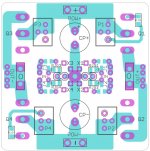
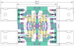
Balanced Cubie with CFNI
(New buzzword - Configurable Feedback Network Interconnection)
Intended use - phones.
PS
Is it possible to use Fairchild 2N54**/MMBF54** as JFETs?
Enough for phones only, speakers not necessary.
(New buzzword
- Configurable Feedback Network Interconnection)Intended use - phones.
PS
Is it possible to use Fairchild 2N54**/MMBF54** as JFETs?
Enough for phones only, speakers not necessary.
Attachments
Since it's been decided that a small LU1014 based circlotron will be built and I need a 4 secondary transformer for that project, Cubie got a whole new PSU - a Sedlbauer 200VA potted toroid (2 x 15V secondaries) followed by a IRFP044N based cap. multiplier. It's on since yesterday and the change is not big, although noticeable - the presentations is a bit more cleaner and more defined (noticeable in big orchestral recordings) with a same gentle overall signature. So, it can be considered as an upgrade.
Here is the sch. and a couple of pics (big 0R1 ceramic resistors in the negative power rails are there just to check the bias current - they were removed after the measurement):
Hi Juma.
This PSU, is it capable of delivering ~1,4A ? (mono psu for one channel miniAlephJ)
I am asking because it's looks very interessting for my Mini AlephJ build
Regards; Jesper.
Hi lykkedk,
that PSU will deliver about 6A (with 200VA transformer) and yes, mosfets in cap. multipler will need some heatsinking - Pd of each of them equals to Vgs x Id.
You can use it for Mini A, no problem.
Regards
Cool...
What about the MBR745 diodes? Do they need sinking?
Also Juma, do you know how much ripple it will give me with load of, say 2,8A? -You can see i have attached a sim. of an normal bigdumb psu
And last quistion, the 1R resistors, are they 1w, 0,25w ?
Jesper.
Attachments
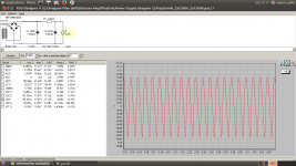
Repeat your PSUD analysis using the values you have in the sch.
You will find that the 4k7 & 2m2F have a time constant that gives a very slow charge to the second 33mF.
The FET will start to get warm while charging up that capacitor and feeding current to the amplifier.
If you draw 2.8A through a diode bridge dropping 1.4V then the bridge needs to dissipate almost 4W. That will be hot. And it will get hot fairly quickly due to the high start up currents into those 33mF caps.
At high currents the bridge will drop more voltage and thus more heat.
At pulsing currents the rms heating effect is higher than for constant currents.
- Home
- Amplifiers
- Pass Labs
- Cubie - small F5 variant with GR grade JFETs and LatFETs