An externally hosted image should be here but it was not working when we last tested it.
An externally hosted image should be here but it was not working when we last tested it.
An externally hosted image should be here but it was not working when we last tested it.
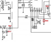
At the driver board, for pins E1 and E2, what is the resistance from the top solder pad to the bottom solder pad for both E1 and E2?
From the top side of the board for E1 and E2, what is the resistance to the gate resistors on both sides of the amp?
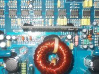
One of the resistors near the FETs appears to have a cracked solder joint. Check all in the area carefully.
From the top side of the board for E1 and E2, what is the resistance to the gate resistors on both sides of the amp?
One of the resistors near the FETs appears to have a cracked solder joint. Check all in the area carefully.
If you read the same resistance from E1 to all of the gate resistors that it drives as you do for E2 and all of the gate resistors that it drives, the problem is likely on the driver board.
I'm assuming that you've confirmed that there are no solder bridges on the FETs.
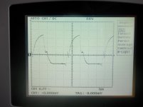
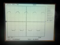
If you have a current limiter or if the FETs heat up slowly enough, check the drive signal at the gate legs of the FETs to confirm that all FETs have the same drive signal.
I'm assuming that you've confirmed that there are no solder bridges on the FETs.
If you have a current limiter or if the FETs heat up slowly enough, check the drive signal at the gate legs of the FETs to confirm that all FETs have the same drive signal.
Now, I replace this components.
Power supply:
IRF1010E all
driver board transistors and lm293
Amplifier:
IRFP250N all
driver board 1D and 2Ds and all ICs.
Two suppressor diode and 1ohm 2w resistor.
The amp is working and hear the music, but faint low-frequency signal beeps sits and reviews about the speaker crackle quarter volume. The low frequency signal strength does not change.
Is this op-amp problem?
http://www.youtube.com/watch?v=sWmw9deZyx8
Last edited:
") But the output driver too very similar! Hifonics board with double irs.
But the output driver too very similar! Hifonics board with double irs.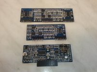
- Status
- This old topic is closed. If you want to reopen this topic, contact a moderator using the "Report Post" button.
- Home
- General Interest
- Car Audio
- Crunch GTX3000D