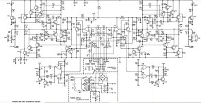
A Crown Powerline 2 (earlier version) came to me with a shorted output and a few other smoked components, Specifically, the Q113 output was shorted, Q110 was blown apart, and R129 was burned up. I replaced Q113 and Q108 with new MJ15015 outputs, installed a 2N3906 for the 2N4125 at Q110, and replaced R129. No other components tested as faulty.
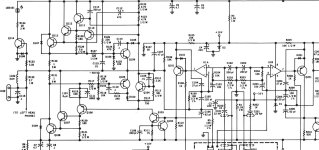
The amp powered up ok with a DBT, and also directly to the mains. However, as soon as I attached my 8 ohm dummy load, I'm seeing pretty significant oscillation in the left channel. I assume that I may be seeing the underlying cause of the original damage. I need more experience solving oscillation issues, so it looks like I have my opportunity. I've attached a portion of the schematic showing the left channel amplifier section. Any direction as to where to start would be appreciated.

The amp powered up ok with a DBT, and also directly to the mains. However, as soon as I attached my 8 ohm dummy load, I'm seeing pretty significant oscillation in the left channel. I assume that I may be seeing the underlying cause of the original damage. I need more experience solving oscillation issues, so it looks like I have my opportunity. I've attached a portion of the schematic showing the left channel amplifier section. Any direction as to where to start would be appreciated.

BSST: Yes, I used my scope to measure the voltage of the sine wave the amp is oscillating. I checked C103 out of circuit, as well as the traces, and all is good there. I also went ahead and checked the rest of the electrolytics in circuit with my Peak Atlas ESR70 just to make sure nothing was open or shorted. The only two I couldn't test in circuit were C5 and C7.
indianajo: I'll check the traces around those caps.
indianajo: I'll check the traces around those caps.
If the amp is stable without a load, I suggest measuring its frequency response and gain. That might give insight.
A different tack is to look at the 220Hz oscillation and how it presents in various parts of the circuit. [Be sure to use x10 scope probes to ensure low capacitance loading from the probe.] In particular, look at how feedback from the output appears at U1A, and at either side of C103. What is opamp pin 1 amplitude peak-to-peak vs. output at PA output?
Bias to U1A + input arrives via R104 which is bootstrapped from C103. This is relatively unusual, and may make the circuit more susceptible to mischief. What is behavior at U1A output, pin 1. Does the oscillation appear on the + input, U1A pin 3 ? Does the input gain control have any effect on oscillation? Try shorting pin 3 to ground. Any change?
BTW, what opamp type is U1?
Thanks.
Some updates before I follow through with the suggestions you two have made, since what's going on now may influence next steps.

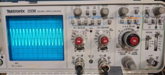
In case it isn't clear from the photo, the time base is .05µs. And while I may have only had Ch1 selected in the shot, it's the same for both channels. I'm also seeing something similar, though not exactly the same with no load connected.
- I ended up replacing C103 since I had already removed it for testing. This also means the solder joints were redone in the process.
- I swapped the 2N3906 I had installed at Q110 with the 2N4125 at Q210 to see if the former sub was causing issues in the left channel, figuring if the problem moved to the right, I'd know.

In case it isn't clear from the photo, the time base is .05µs. And while I may have only had Ch1 selected in the shot, it's the same for both channels. I'm also seeing something similar, though not exactly the same with no load connected.
I estimate the oscillation frequency is just under 30MHz--- agree?
That's certainly an RF oscillation. Is the 220Hz oscillation gone? There's a 0.1uF (C116) across the speaker terminals, and 30MHz is probably above its series self-resonance.
The upper output stage is a NPN triple emitter (3EF) follower and the lower is double NPN emitter follower driven by a PNP driver in local complementary feedback arrangement. The former has a reputation for being oscillation prone, as do complementary feedback pairs. The Q106/Q107 cascade adds further complexity.
I notice you're using coax cables connecting the scope. I recommend a x10 probe and using the shortest ground clip that's manageable for probing. Poke around in the output stages, looking for spots where oscillation is largest for insight to oscillation path, and especially on the supply rails. This is a tough problem. Look at bypassing. Note that C4 is 0.02uF vs. C6 is 0.1uF. Where are they positioned? Ideally near the output leads, with short leads to ground. Use of "base stopper" resistors is a common practice to avoid instability. Look at recommendations from Bob Cordell.
Good luck!
If the electrolytic bypass caps have gone bad, you can certainly pick up an RF oscillation. Collector of Q112/13 and emitters of Q107/08 need to be low impedance from DC to light - especially with this output stage. If they are running Q113 and 108 fully class B in cutoff, their drivers see a horrible capacitive load.The electrolytic caps do not prevent oscillation. The ceramic or mica caps do. A capacitor meter that measures 20-1000 pf would be useful. Ceramic and mica do not fail often, but factories do make bad solder joints.
If that oscillation is only in the left channel and not present in the right channel then the stereo-mono switch contact resistance may have increased.I'm seeing pretty significant oscillation in the left channel.
What happens if you put the amplifier in mono mode?
Another possibility - C115 is very small (0.01uF) but printed in schematic as lytic.
Such small capacitors tend to dry up.
The characteristic frequency of R127/C115 is very near 200...220 Hz in case C115 has lost some of its capacitance:
https://www.omnicalculator.com/physics/rc-circuit
Just a shot in the dark
Such small capacitors tend to dry up.
The characteristic frequency of R127/C115 is very near 200...220 Hz in case C115 has lost some of its capacitance:
https://www.omnicalculator.com/physics/rc-circuit
Just a shot in the dark
Ok, I had a chance to spend more time with this. I started by looking at U1, which is an NE5532.
The oscillation appears on the output for the left channel, pin 1, as well as the inputs of both channels, 3 and 5, though lower amplitude. There's indistinct noise on the right channel output, pin 7, even though there had been oscillation there previously. Grounding pin 3 doesn't have any effect, nor does adjusting the gain.
madis64: Good thought about the Mono/Stereo switch. I cleaned it with some Deoxit D5, fwiw. The oscillation is present with the switch set to Mono. And C115 is a ceramic, despite the schematic marking.
Yes, I replaced C103 with a new 100uF cap.
So you're saying to connect the wipers from the left and right gain pots?
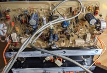
I've attached a photo of the main board. One challenge with this amp is that there are no component ID marking on the board and no image in the service manual showing component locations, making it tedious to go back and forth from foil side to component side trying to figure out what's what.

Yes, as a starting point to make sure that both channels are getting the same input signal.So you're saying to connect the wipers from the left and right gain pots?
Also I would replace the input capacitors for film ones and after that just swap the opamps (they are in the sockets so no soldering involved) for "anything that is in your drawers" to eliminate them from the equation.
- Home
- Amplifiers
- Solid State
- Crown Powerline 2 Oscillation
