In the first instance, the 'easy way' (for me) is to perform filtering in software (Linux); my (FireWire, 24-bit) audio interface has 8 outputs and I have enough amplifiers knocking around. It should be an interesting experiment. If I like what I hear, I'll know it's worth pursuing the idea further.
That'll have to wait as I broke off from a couple of other projects when the tweeter failed, I'd like to get back to those (which should result in higher-quality vinyl playback than I've ever had, which in turn will probably mean I'll want to further improve the amp(s) and speakers...)
That'll have to wait as I broke off from a couple of other projects when the tweeter failed, I'd like to get back to those (which should result in higher-quality vinyl playback than I've ever had, which in turn will probably mean I'll want to further improve the amp(s) and speakers...)
Don't be sorry nor apologise for having a different opinion.Sorry..........That is easily achieved with Axial format caps, by using caps of the same body length.
Soldering the end leads of axial caps, whether of different body or not, must end up exactly the same length from common to common.
I have never heard that "length" affect sound signals differently from test signals.
Hi,
For the benefit of anyone who's interested, I've attached the schematic of the 44 crossover. I reverse-engineered this from a pair with cabinets date-stamped December 1976, all drivers with 'AK' date codes, corresponding with January 1977. I purchased these from the original owner, to the best of my knowledge they've never been apart (until I took them apart) and don't appear to have had any components replaced since manufacture.
A few notes...
Inductor DC resistance meaurements were taken with my 'Solartron 7150 plus' 6-digit bench DMM using the '4-wire' method to ensure accuracy and eliminate errors caused by test-lead resistance.
The inductors were measured by determining the resonant frequency of a parallel-resonant circuit consisting of the unknown inductor and a capacitor which measured 1.536 µF on my Beckman 'DM25L' DMM, then calculating the inductance. As I don't know how accurate this DMM is for capacitance measurements, I cannot guarantee absolute accuracy.
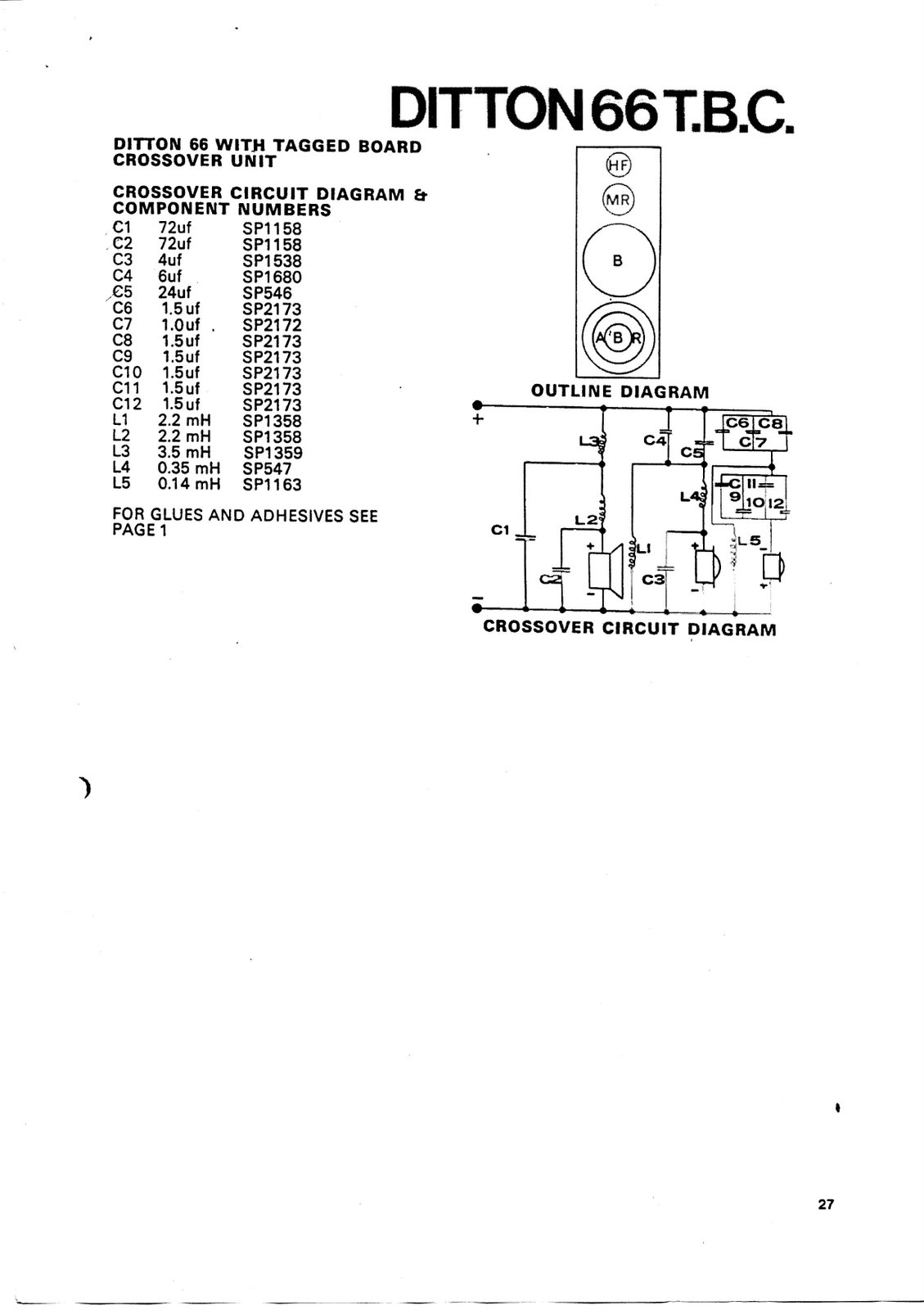
However, one (and only one) of the inductors; L5, Celestion part no. SP1163, is common to the 44 and 66 crossover. The 'Ditton 66 T.B.C.' schematic states that this is 0.14 mH. This broadly agrees with my measurements so it's (arguably) reasonable to assume the rest of the measurements aren't too far off.
The values on the diagram are 'best guess' based on measuring the components in both crossovers. The values weren't consistent, clearly there's some manufacturing tolerance (as well as possible measurement errors) but I'll list the calculated values for the inductors in each crossover, rounded to three digits.
I hope this is useful for someone; I've ended up working this out as I've never found a complete schematic for the 44 anywhere and thought I'd share my findings.
- L1: 2.10 mH and 2.08 mH
- L2: 2.09 mH and 2.10 mH
- L3, 3.28 mH and 3.16 mH
- L4, 0.653 mH and 0.661 mH
- L5, 0.139 mH and 0.140 mH
Regards, Kat
Kat, this is super helpful. Many thanks. I'm still getting over the shock of there being a woman on this forum, and more shocked that she's into electronics and hi-fi to a substantial extent! Lucas
Last edited:
So Alan,
I'd like to wind myself some inductors at some point. It would be nice to be able to reliably inform Ditton 44 users of a proven correct way to upgrade inductors to Ditton 66 levels.
I will need 4x 2.1mH for the midrange shunt inductors and for the bass series, and 2x 3.2mH for the bass series (Thanks to amazing Katherine for this).
The only question that remains is the thickness of the copper to be used and the dimensions of the spool to wind upon. For this, I think the best thing is to copy that of the 66s, which have similar but not identical values.
Could you, or indeed any Ditton 66 Mk1 owner let me know the copper thickness and spool size of the mid shunt and both bass inductors when you next delve into the crossover please...
Many thanks (and on behalf of all upgrading 44 owners in perpetuity!)
Lucas
Hi,
A bit of progress to report:
One cabinet 'adjusted' for the SEAS tweeter. Tweeter fitted with wires brought out through one of the original tweeter clamp holes. Bass section caps replaced. Tweeter section components removed and fitted to a bit of tagboard sat on top of cabinet, for easy tweaking.
Gave it a try with the tweeter section components unchanged. It has no right to sound this good. Clearly, the SEAS tweeter is a vast improvement.
It currently sounds like a two-way system that's "not quite right", I can "hear the join". As I'd expected, there's a step up in level above the crossover frequency. But not much.
Next, rearrange the living room a bit and get response plots (of this and the unmodified and supposedly "working" one.) My ears say one thing, let's see what the test gear says.
My partner remarked, after a quick test turned into a several-hour listening session, "I think you're about to take our hi-fi system to a whole new level." That's after listening in mono via a badly-positioned speaker with a tweeter crossover we both know and can tell isn't right. Promising!
Kat
Hi,
Gave it a try with the tweeter section components unchanged. It has no right to sound this good. Clearly, the SEAS tweeter is a vast improvement.
Kat
That's exactly what I reported when I swapped the HF2000 for the Seas 19TFF1. It's great that you've done the same thing and also reported the significant improvement. Tweeter quality has improved in leaps and bounds since 1977, and this Seas is notoriously excellent, so it's hardly surprising. I will be replacing the second series cap with a 10uF soon, as per Alan's calculations, which may be all that is required. I found that I didn't need a resistor or any attenuation for this tweeter - the level was just right for my 44s.
I am really happy with all of the drivers now. All sterling performers to my ears.
Before you buy
Hi Kat and Lucas,
before either of you buy anything ... wait, I'll Post some short-cuts as soon as I can get back here.
Resistors are cheap, but capacitors cost more, thus what I will advise ...
including some suitable resistors for attenuation.
Taking on so much in 2 threads I currently don't have time to keep up !
Resistors and Capacitors for SEAS tweeter
Hello again,
I have a little time available, thus as follows:-
To hear the SEAS H737 tweeter in somewhat closer to flat response than will be occurring currently with the treble filter in the 44
-{and 66}- crossover, connect a 27 ohm/minimum 5 watts, {though higher power may be better},
wirewound resistor in parallel with the tweeter, eg: across the output terminals of the treble filter.
The treble will still be higher level than mids, but less of a peak and dip response than currently.
Better will be to attenuate, as follows:-
Parallel resistor 18 ohms plus a Series connected 0.68 ohm resistor from the junction point of the 18 ohm and tweeter over to the output of the 6uF capacitor will reduce by about 1dB.
Parallel 18 ohms plus Series 0.82 ohms will reduce by a little over 1.25dB.
Parallel 15 ohms, Series 0.82 ohms, reduces by 1.35dB.
Parallel 15, Series 1 ohm, reduces by a little over 1.6dB.
Parallel 12 ohms, Series 1.2 ohms, reduces by 2dB.
Which to start with ?
Reduce by 1.25 <--> 1.35dB if you want slightly brighter treble than Flat Response.
Reduce by 1.6dB, I estimate is likely to give close to Flat Response - if the SEAS specs are close to accurate.
Reduce by 2dB if you want similar treble to the original Celestion balance -
- "similar" - it will be better quality, and level response to about 16kHz instead of the slight roll-off from 10kHz of the old HF2000.
For the Series resistors use Welwyn WP4S series if possible, otherwise WA84 or W21 series.
For the Parallel resistors use Welwyn W22 - I doubt the higher power W23 will be necessary for the resistors to remain cool, unless you are playing your l'speakers very loudly.
If you can't buy from Farnell or another Welwyn seller, then use 3 <--> 5 watt wirewounds for Series, and 7 <--> 10 watt wirewounds for Parallel.
The resistors will render the sound more listenable, but not flat response,
because that crossover's treble filter is designed for a tweeter that has a rising response below 5kHz,
and a larger Impedance peak at its Fs than the SEAS has.
I estimate for the SEAS that 3.6uF will be optimum or close to ...
and 3.6uF can be bought in UK in the Jantzen Cross Caps -{which you have others of Lucas}.
For output capacitor, don't buy anything new yet, until further experiments are done.
***********
Lucas,
for output cap, you can use your 3.9uF and connect it in Parallel with the installed 6.2uF, which will sum to 10.1uf - close to the likely optimum -
and listen to decide what you may prefer to do next.
The Jantzen cross caps in 3.9 and 6.2 are apparently of equal length - correct ? - and if so then they will have equal Pulse Rise Times thus not distort the Transient Response of the music.
EDIT: OK, put the 10uF MKP in there, and leave the 3.9 as input till you listen with resistors, then decide what you may prefer to do next.
Are your 3.9 and 6.2 Cross Caps of equal length ?
I'll post about inductors next time - better can be achieved than simply copying the original Celestion 66 inductors if you are going to the trouble of winding or buying new.
***********
Kat,
simplest is for you to connect all the old treble caps in Parallel and use them as the output capacitor, as such will sum to 10uF - good enough for you to continue listening and measuring response with to decide further.
What to buy for new Input cap depends on the type of sound you want.
If you want bright and fairly upfront presentation then buy the 3.6uF Jantzen Cross Cap.
If you want a more spacious sound-stage, then various reports are that the Jantzen "Superior Z-cap" -{also listed as "Z-Superior Cap"}-
are audibly better for such than Cross Cap.
{There are no recommendations now for the "Standard Z-cap" since the introduction of Cross Cap.}
Superior Z-cap is not available in 3.6uF, thus you would have to buy two of 1.8uF and connect in Parallel.
I have not used these Jantzens, thus am relying on reports by a few users who seem reliable -{not all listeners are reliable}.
I use Clarity Cap PX series, but to get those in suitable values you will have to buy via Mail-order from USA.
Clarity Cap's larger physical size SA series are available in 1.8uF in UK from:
amplifier valve kits, HIFI pre-amplifiers, speaker kits,AMP Parts, upgrade components
at not excessive price.
I recommend that you do not use Solen/SCR/Chateauroux capacitors with the SEAS tweeter because it is transparent enough to display their audible limitations.
Wilmslow Audio "supersound" capacitors are Solen/SCR.
If you would like to discuss other brands, etc ... please post here.
***********
Also Kat,
with all the test equipment that you have, if you can measure the Impedance minimum of the SEAS tweeters at whatever frequency such occurs in the useable portion of their bandwidth, {or nearest frequency to}, then please do and Post here - for both samples as there may be variation.
See the minimum on the SEAS Impedance Plot at about 4kHz or a little above
{I forget the frequency exactly, and I don't have the plot with me here}
which seems to be a little greater than 7 ohms.
I have used 7.2 ohms for my calculations for the resistors, but if your samples are significantly different there then I would like to calculate again for better accuracy.
Last edited:
Hi Alan,
I've also got a couple of 8.2µF knocking around from something else, all the original Erie caps and a box of 70 1µF Russian caps that'll do for the odd experiment - I'm not buying anything decent until I've established what's needed. (I've also got a reasonable selection of w/w resistors in the 0.5Ω to 100Ω range; not all values but enough to make up pretty much anything with series/parallel combinations.)
Sound... My curse is that I've heard multitracks and masters in studio control-rooms. It's led to my aim with my systems being "as close as possible to what the engineer heard in the control-room". But this is with a near-zero budget which precludes having a large active Dynaudio monitor system in the living room. Hence I do the best I can with what I've got, it keeps getting better (and it's both fun and educational.)
Kat
That's one of the things I was intending to do; the SEAS datasheet isn't all that clear. At the very least, I'll sweep a generator up and down and find the minimum. If I'm feeling enthusiastic, I'll take more measurements and plot them.with all the test equipment that you have, if you can measure the Impedance minimum of the SEAS tweeters at whatever frequency such occurs in the useable portion of their bandwidth, {or nearest frequency to}, then please do and Post here - for both samples as there may be variation.
I've also got a couple of 8.2µF knocking around from something else, all the original Erie caps and a box of 70 1µF Russian caps that'll do for the odd experiment - I'm not buying anything decent until I've established what's needed. (I've also got a reasonable selection of w/w resistors in the 0.5Ω to 100Ω range; not all values but enough to make up pretty much anything with series/parallel combinations.)
Sound... My curse is that I've heard multitracks and masters in studio control-rooms. It's led to my aim with my systems being "as close as possible to what the engineer heard in the control-room". But this is with a near-zero budget which precludes having a large active Dynaudio monitor system in the living room. Hence I do the best I can with what I've got, it keeps getting better (and it's both fun and educational.)
Kat
Hi,
I've been experimenting...
First, I made two assumptions. One was that the impedance of the HF2000 around the crossover frequency is 4.8Ω (based on an impedance plot of four of them, posted in the '66' thread a while ago.) The other was that the impedance of the SEAS unit around the crossover frequency is 7.5Ω (based on the plot in the SEAS datasheet.)
With the SEAS driver connected to the original treble filter, the filter doesn't have the load it was designed for. What happens if I 'fix' that?
Two 27Ω (2% 10W) resistors in parallel with the SEAS driver works out as 4.8Ω.
This sounded better integrated, the tweeter sounded less obviously separate from the bass/mid drivers. There was still an obvious step up in level, though.
Next, I connected the bass/mid crossover input to one channel of an amplifier and the treble crossover input to the other channel. Each channel was fed from separate outputs on a 4-channel audio interface (with L+R source summed and routed to both of these outputs.) Now I could wind the treble level up and down and, usefully, the DAC levels in 'alsamixer' are in dB.
3dB attenuation of the treble output (w.r.t. the bass/mid output) produced the most natural-sounding results, the step in level disappeared. Comparing with the unmodified 44, it sounds a little brighter but not excessively so and much more detailed. It's very easy to pick out individual instruments and sounds, even those low down in the mix. Male and female vocals sound natural and convincing. Particularly well engineered/produced recordings have an amazing sense of depth to them. (Bear in mind this is currently a monophonic system with one centrally-placed 44...)
So, 3dB it is. The back of an envelope and the parts available meant another two 27Ω resistors in parallel with the tweeter (so 6.75Ω in parallel) and three 0.47Ω in series (1.41Ω total), between the crossover output and tweeter.
Results? Terrible. The odd thing is it was nothing obvious. Just the music ceased to be engaging. Two-dimensional, flat, boring, lifeless, veiled...
I've gone back to the previous bi-amped mono arrangement; all original Celestion treble section components, a pair of 27Ω in parallel with the tweeter and the treble level reduced by 3dB before it hits the amplifier.
OK, it's a start; that's one thing which works and another which doesn't")
Kat
I've been experimenting...
First, I made two assumptions. One was that the impedance of the HF2000 around the crossover frequency is 4.8Ω (based on an impedance plot of four of them, posted in the '66' thread a while ago.) The other was that the impedance of the SEAS unit around the crossover frequency is 7.5Ω (based on the plot in the SEAS datasheet.)
With the SEAS driver connected to the original treble filter, the filter doesn't have the load it was designed for. What happens if I 'fix' that?
Two 27Ω (2% 10W) resistors in parallel with the SEAS driver works out as 4.8Ω.
This sounded better integrated, the tweeter sounded less obviously separate from the bass/mid drivers. There was still an obvious step up in level, though.
Next, I connected the bass/mid crossover input to one channel of an amplifier and the treble crossover input to the other channel. Each channel was fed from separate outputs on a 4-channel audio interface (with L+R source summed and routed to both of these outputs.) Now I could wind the treble level up and down and, usefully, the DAC levels in 'alsamixer' are in dB.
3dB attenuation of the treble output (w.r.t. the bass/mid output) produced the most natural-sounding results, the step in level disappeared. Comparing with the unmodified 44, it sounds a little brighter but not excessively so and much more detailed. It's very easy to pick out individual instruments and sounds, even those low down in the mix. Male and female vocals sound natural and convincing. Particularly well engineered/produced recordings have an amazing sense of depth to them. (Bear in mind this is currently a monophonic system with one centrally-placed 44...)
So, 3dB it is. The back of an envelope and the parts available meant another two 27Ω resistors in parallel with the tweeter (so 6.75Ω in parallel) and three 0.47Ω in series (1.41Ω total), between the crossover output and tweeter.
Results? Terrible. The odd thing is it was nothing obvious. Just the music ceased to be engaging. Two-dimensional, flat, boring, lifeless, veiled...
I've gone back to the previous bi-amped mono arrangement; all original Celestion treble section components, a pair of 27Ω in parallel with the tweeter and the treble level reduced by 3dB before it hits the amplifier.
OK, it's a start; that's one thing which works and another which doesn't
Kat
Hi Alan,
Just to clarify...As a starting point, I will change the 6uF Jantzen cap to the 10uF MKP. I realise that I am left with a 3.9uF cap where a 3.6 is required, but for now, I will leave that to evaluate.
I will buy some 15 Ohm W22 or W23 Welwyn wirewounds for paralleling with the Seas 19TFF1.
I will buy some 1 Ohm WP4S Welwyn wirewounds for series attenuation between the 10uF cap and Seas input.
On paper this should give me close to a flat response (-1.6dB) IF the tech-specs are correct, right?
For me, that's a good starting point. I order from Farnell about once a week at the moment, as I'm building hi-fi like crazy, so it's no hassle to buy more resistors later if needed.
Just thought I'd check with you first.
Hi,
After realising I'd made a stupid mistake I've scribbled more calculations on a different envelope...
(In my defence, I had 'pulled an all-nighter'; several pints of coffee is a poor substitute for sleep.)
So... I'm now currently conducting listening tests with 3 x 27Ω in parallel with the driver (Russian mil-spec 2% 10W), one 1Ω between crossover and driver (Welwyn W23), original Celestion crossover circuitry otherwise (4µF, 140mH, 6µF). Results seem favourable.
My (rough) computer simulation suggests this has ironed out a lump (9dB @ 15kHz) in the original response, produces a slight rise (~3dB up @ 20kHz) but has, overall, flattened the response off. That includes a flatter combined response of the mid and treble drivers. Note that this is all simulated electrical response (using simplified driver models, a resistor and an inductor in series), not real-world acoustic response.
However, it seems to translate into something which sounds good - and is a vast improvement over the unmodified one (without really sounding different; it's still a Ditton 44.)
If I can drag myself away from playing music (difficult!), I think I'll modify the other 44 and see what this is like in stereo.
Reading back, I note that Alan and myself seem to be converging on the same point from different directions; this is probably a good sign
Oh; has anyone else noticed the crossover frequency is more like 'just over 4kHz', rather than the 5kHz suggested by Celestion promotional material?
Kat
Last edited:
Also, Alan...if copying 66s is not optimum, can you tell me about the best way to make my 2.1mH and 3.2mH inductors.
If buying a cheap inductance meter, hubs and wire is the same price as buying them off the shelf, I'll make them for sure.
I should say that high volume "congestion" is quite apparent in these speakers. The sound tends to get muddy and a touch distorted in the broad range of the low mids when played loud, and it's partly this saturation of the bass circuit inductors which I suspect causes it. If there's a way to fit a grade of inductors that absolutely won't saturate in a 15' square room, that would be awesome.
Hi Lucas,
How powerful are your amplifiers?
This isn't something I've noticed; when testing a pair of 120W amplifiers I'd been modifying, I once tested at quite high level. Some distortion was present - until I put a pair of ear-defenders on!
I've also observed transients being clipped on a 'scope when using a 30W amplifier at 'average listening level' (which measured at about 4W.) This didn't sound obviously distorted, more just a muddying and smearing of detail.
Amplifiers I'm using in rotation on this system:
Room size here is approximately 12' square, by the way; with two alcoves either side of the chimney breast and a bay window. Speakers are opposite the window with the sofa in the bay (and heavy velvet curtains which are seldom opened) and the fireplace/alcoves are on the left as you're sat on the sofa. (Too small, really; and acoustically 'tricky' but I've managed to make it work.)
Kat.
How powerful are your amplifiers?
This isn't something I've noticed; when testing a pair of 120W amplifiers I'd been modifying, I once tested at quite high level. Some distortion was present - until I put a pair of ear-defenders on!
I've also observed transients being clipped on a 'scope when using a 30W amplifier at 'average listening level' (which measured at about 4W.) This didn't sound obviously distorted, more just a muddying and smearing of detail.
Amplifiers I'm using in rotation on this system:
- Marantz 1150 - 85W/ch.
- Musical Fidelity B1 - 32W/ch. but with a slightly crafty PSU circuit which allows delivery of 80W/ch. pulse.
- The two 120W amps mentioned above.
Room size here is approximately 12' square, by the way; with two alcoves either side of the chimney breast and a bay window. Speakers are opposite the window with the sofa in the bay (and heavy velvet curtains which are seldom opened) and the fireplace/alcoves are on the left as you're sat on the sofa. (Too small, really; and acoustically 'tricky' but I've managed to make it work.)
Kat.
My amps are LM3875 Gainclone amps - much like an average 50WPC domestic power amp, and very clean and musical.
I realise now that it may have been the fault of certain compressed MP3s that caused me grief. I listen to a lot of lossless files and they are considerably cleaner. Muddiness of such MP3s shows up particularly at higher volumes for some reason - perhaps the reason is too obvious to mention - it's louder!
It was whilst listening to a very loud playing of Abracadabra by Steve Miller Band (my 4 year old loves to dance, so I play him what caught my attention when young, and he loves it) that it sounded quite awful, and had my wife come in from the kitchen telling me it was too loud. Checking now, it is a 128kbps MP3 file I downloaded from the interweb, so yes, perhaps it is to blame.
When music distorts, yes, it's too loud very very quickly!
I would still like air core inductors at some point though.
I always thought that the Marantz 1150 is a lovely amp, by the way. It looks way cool too
Aha, the curse of mp3...
(I notice the difference between 320k mp3 and FLAC; 320k isn't too bad but FLAC is better.)
I'm still curious as to what contribution those ferrite-cored inductors are making, and at what level it starts to get serious. As I'll shortly have the other 44 crossover on the bench, I'll hook the bass section to a 120W amp, load the output with a resistor, and have a play around with my distortion analyser (Sound Technology ST1700B.)
My current opinion (and it's only an opinion, I may be wrong) is that replacing the ferrite-cored inductors with air-cored inductors won't really make much difference. The problem is there's a 4th-order low-pass filter between the amp and the driver. Replacing it with 3rd/2nd/1st is inadvisable as Celestion must've used a 4th-order filter for a reason (the bass driver gets 'a bit funky' somewhere above the crossover frequency?) and, though 4th-order filters are 'unpopular', replacing it with 3rd/2nd/1st would mean replacing the bass driver as well. Then one would have to tweak the mid crossover to integrate the mid with the bass, maybe replace the mid as well. Oh, and replace the cabinet with one of the correct volume to match the new bass driver...
This turns into "grandfather's axe" rather rapidly; "Yeah, they're Celestion Ditton 44s; I just replaced all three drivers, redesigned the entire crossover and built a new cabinet..."
I'm fairly happy with what I'm listening to at the moment (I just need to do the same mods to the other one.) I haven't had to change much, it didn't cost much, and it sounds 'the same but better' (more transparent, more detail, clearer, cleaner.)
Losing the 4th-order passive filter should make a huge difference. That means connecting the driver directly to an amplifier and sticking a 4th-order LPF ahead of the amp, which is... non-trivial.
The revised 'active 44' plan involves:
I need to modify the DN800 filter cards for the appropriate crossover frequencies (it's currently configured as four 2-way crossovers), fit more terminals to the 44s and rewire...
Kat
(I notice the difference between 320k mp3 and FLAC; 320k isn't too bad but FLAC is better.)
I'm still curious as to what contribution those ferrite-cored inductors are making, and at what level it starts to get serious. As I'll shortly have the other 44 crossover on the bench, I'll hook the bass section to a 120W amp, load the output with a resistor, and have a play around with my distortion analyser (Sound Technology ST1700B.)
My current opinion (and it's only an opinion, I may be wrong) is that replacing the ferrite-cored inductors with air-cored inductors won't really make much difference. The problem is there's a 4th-order low-pass filter between the amp and the driver. Replacing it with 3rd/2nd/1st is inadvisable as Celestion must've used a 4th-order filter for a reason (the bass driver gets 'a bit funky' somewhere above the crossover frequency?) and, though 4th-order filters are 'unpopular', replacing it with 3rd/2nd/1st would mean replacing the bass driver as well. Then one would have to tweak the mid crossover to integrate the mid with the bass, maybe replace the mid as well. Oh, and replace the cabinet with one of the correct volume to match the new bass driver...
This turns into "grandfather's axe" rather rapidly; "Yeah, they're Celestion Ditton 44s; I just replaced all three drivers, redesigned the entire crossover and built a new cabinet..."
I'm fairly happy with what I'm listening to at the moment (I just need to do the same mods to the other one.) I haven't had to change much, it didn't cost much, and it sounds 'the same but better' (more transparent, more detail, clearer, cleaner.)
Losing the 4th-order passive filter should make a huge difference. That means connecting the driver directly to an amplifier and sticking a 4th-order LPF ahead of the amp, which is... non-trivial.
The revised 'active 44' plan involves:
- Klark Teknik DN800 (as I've already got one.)
- Musical Fidelity B1 for high.
- Sansui AU-317II for mid.
- Marantz 1150 for low.
I need to modify the DN800 filter cards for the appropriate crossover frequencies (it's currently configured as four 2-way crossovers), fit more terminals to the 44s and rewire...
Kat
Air-cored inductors...
I've just used this online inductor calculator to work them out (and find out roughly how much wire would be needed.)
Aiming to get the same (or slightly lower) DC resistance as the ferrite-cored inductors means using 1.33mm wire, about 256m of it in total for all six inductors.
A quick look on eBay and I find 4kg of 1.32mm enamelled copper wire (about 328m), for £49.96 + £8.96 P+P.
I don't think I'll bother winding air-cored inductors any time soon; £60 would get me a few more s/h records...
Kat
Last edited:
- Status
- This old topic is closed. If you want to reopen this topic, contact a moderator using the "Report Post" button.
- Home
- Loudspeakers
- Multi-Way
- Crossover nightmare!!!!!!!