I am using Vance Dickasons formulas for a 3 way APC crossover. After plugging in the numbers into the formula using my measured impedances, I get an 8mH coil for the lowpass section. My question is this : The voice coil inductance for my woofer is 3.1mH. Should I subtract the 3.1 from the 8mH to get the value coil I use or should I simply use the 8mH ? This same question applies to my midbass filter as well. Any assistance will be appreciated........Respectfully........ Omni
I believe you simply use the 8mH coil. If one of your lowpass crossover points falls in an area where the impedance of the driver is already rising quickly, consider implementing an impedance equalization circuit.
Link to some useful calculators - http://www.mhsoft.nl/spk_calc.asp
Dan
Link to some useful calculators - http://www.mhsoft.nl/spk_calc.asp
Dan
Hi Omni,
I'm a beginner, but I found a very useful page here:
http://www.lalena.com/audio/calculator/apcxover/
(the audio section from the home page has lots of useful
stuff too)
I'm trying to do a 3way APC from the 'cookbook' as well,
and received some very helpful replies to my post
"bandpass formulas dilemma - a newbie Q"
hope this helps, Grant
Grant,thanks for the link, I checked it out and its pretty cool.What I am trying to determine was not on the site but it still is helpful. Lets say you have a woofer with a voice coil inductance of 3 mH........ now, the calculation based on impedance renders an inductor of 8mH for the lowpass filter. Now that the woofer already has 3mH inductance, would this make the inductor for the crossover to be 5mH thereby adding up the Voice coil 3 mH inductance to 5 mH to equal 8 ? I perhaps hope some of the more learned audiophiles on this site might be able to share their experience. Also, I am hoping to find out what method to calculate a zobel impedance compensation network works the best, as there are a variety of theories, any input out there, fellow speakerbuilders ? Respectfully..........Omni
I am not familiar with the formulas that you use, but assuming that the filter is first order you should in principle subtract the inductance of the woofer. There is a problem with this, however, due to the nature of the voice coil inductance: it is frequency dependant, larger at low frequencies and smaller at high frequencies. The number stated in the datasheet is only valid at a single frequency (and it is often not stated which frequency this is).
I suggest that you try to simulate the entire system instead of blindly relying on formulas for the crossover. Crossover design is tricky and any attempt to reduce it to a couple of formulas is bound to produced results that were not intended.
I suggest that you try to simulate the entire system instead of blindly relying on formulas for the crossover. Crossover design is tricky and any attempt to reduce it to a couple of formulas is bound to produced results that were not intended.
Svante :Thank you for your post. I always appreciate feedback, as I am certainly NOT extremely experienced. At any rate, the slope will be 12bB per octave. Here are my thoughts on creating my crossover; and maybe you can help ? First, I will be doing impedance measurements with an old tube frequency generator. I have done some preliminary measurements with voltage divider method. I am thinking I may have to calibrate after each measurement to maintain proper voltage readings at each frequency. Does this seem reasonable? I also thought of experimenting with Speaker Workshop......Is this an accurate measurement system ? I have limited finances.........Then put Zobels on the midbass, and tweeter, and re measure impedances, mounted in cabinets. Crossover frequencies of 300, and 3000Hz. 12 dB per octave using APC formulas in Vance Dickasons book. Then tweak to get the sound I am looking for. As I stated, I do not have a lot of money to afford other measurement systems, would rather spend it on decent crossover components. Peerless 830669 SLS 12 inch woofer, SEAS CA15RLY midbass, SEAS 27TDFC tweeter, All good performers with reasonably good characteristics. Cabinet is a pyramid shaped 4 cubic feet sealed for woofer, and about 15 liters, sealed for midbass. 7 degree slanted baffle, all made of 1 inch particle board. I made an earlier post pertaining to this project and TINITUS and a few others convinced me my earlier bass cabinet size was too small, so I decided to start from scratch, and build a larger cabinet. Thank You TINITUS, Johnathon Brite, 5th Element, and others for your insights. At any rate my father passed away, and the project was shelved for a while, hence me not pursuing more info on this forum, but I have returned to gain more insights if possible. Clarity Caps bypassed with Mundorf Supreme silver/oil, 14 guage inductors throughout all of crossover except in low end of midbass in the bandpass, and woofer section. Mills resistors for Zobels and tweeter attenuation, when that time comes. This project has been very time consuming,with several cost overruns, but fun, to say the least, and very enjoyable communicating with you all,on this forum.......At any rate ANYONE else who cares to chime in on this thread, please feel free, I can use the help. This is like Dorothys' house, back in Kansas, in the Wizard of Oz: everything starting out in Black and White, and then Dorothy opens the door of the house after the whirlwind tornado,to experience a whole new world of COLOR. I look forward to that experience when I plug these speakers in and turn up the volume..............But it's still got a little bit of work to be done..........Omni
Svante said:I am not familiar with the formulas that you use, but assuming that the filter
is first order you should in principle subtract the inductance of the woofer........
Hi,
In principle for such simple "cookbook" crossovers this is not true.
In principle you should zobel the driver to be resistive and use
the "cookbook" value for the inductor.
All too trivial though, basically wrong, it may work, it may not,
actually understanding what is going on and the resultant
acoustic slopes including fundamental resonance, driver response,
baffle step and diffraction effects is far more important.
") /sreten.
/sreten.Sreten, I agree with your post, and hopefully I have addressed the issues you have mentioned. I am figuring on a 4th order acoustic slope with the combination 2nd order crossover in my sealed cabinet. Maybe maybe not. At any rate I have treated the baffle edges with a 3/4 radius as per Zaphs website. On the baffle step issue, I am not too concerned. I may have the best of both worlds here... I have made the width of the cabinet a bit wider at the bottom of the pyramid to provide more reinforcement to the bass. It appears these days the designs of narrower cabinets, especially in the woofer section, has brought about the baffle step issue. I have decided to make mine a bit wider. Also, any baffle step I do get may be somewhat of a blessing, as my midbass sensitivity is a bit lower than the woofer. After Tinitus voiced his concern about my cabinet size, I decided to shift gears into a larger design: many hours of drawing prototypes, calculating volumes, to come up with my final design, which I think will be worth it, both in the bass as well as the midbass cabinet. See the specs in my last post. Thank you Tinitus. By the way Tinitus, its funny you mentioned about starting off with a larger coil with the option of removing some wire, because just before I logged on here, today, I was contemplating my future tweaking routine,and that thought came to mind. My cabinets are built, however I have not put the laminate on them yet, also, I will need to put one more brace in them. Tinitus, I will take some photos in the next day or so, and post them here. I know someone mentioned, I think it was you:that a pyramid could get ugly. You are right. You should see some of my preliminary drawings. Alas........the final design worked out beautifully, albeit a bit taller than my original concept, but very pleasing to the eye, as well as acoustically sound. Look for the pictures in the next few days..............Respectfully....Omni
sreten said:
Hi,
In principle for such simple "cookbook" crossovers this is not true.
In principle you should zobel the driver to be resistive and use
the "cookbook" value for the inductor.
All too trivial though, basically wrong, it may work, it may not,
actually understanding what is going on and the resultant
acoustic slopes including fundamental resonance, driver response,
baffle step and diffraction effects is far more important.
Yes, I agree, that's why the "in principle" was there in my post, and the recommendation at the end of the post. It is hard to know how to handle questions like these, it appears as if many people look for equations for how to design crossover filters, and indeed there are quite a few of them around on the web. My opinion is that simple equations never results in the response that you really want, and that you need to either simulate the whole loudspeaker system or do measurements on an actual system and modify the component values until the response is as desired. The impedance and the response of the drivers and also the baffle step all put non-cookbook requirements on the filter.
However, such a response to a person who just has found a bunch of equations on the web probably leads just nowhere. So I tried to answer the question with an "in principle" as a reservation that the line of thinking is at best as good as using a cookbook filter design in the first place. I am not sure whether this is the right thing to do, but that was my thinking behind it, anyway.
Now, as it turns out, the filter was second order, and that makes my line of reasoning not even in principle right, and the conjugate link combined with the full inductance seems more appropriate, but I would still like to recommend the full simulation of the system to include the response of the drivers and the baffle step etc.
omni said:Svante :Thank you for your post. I always appreciate feedback, as I am certainly NOT extremely experienced. At any rate, the slope will be 12bB per octave. Here are my thoughts on creating my crossover; and maybe you can help ? First, I will be doing impedance measurements with an old tube frequency generator. I have done some preliminary measurements with voltage divider method. I am thinking I may have to calibrate after each measurement to maintain proper voltage readings at each frequency. Does this seem reasonable? I also thought of experimenting with Speaker Workshop......Is this an accurate measurement system ? I have limited finances.........Then put Zobels on the midbass, and tweeter, and re measure impedances, mounted in cabinets. Crossover frequencies of 300, and 3000Hz. 12 dB per octave using APC formulas in Vance Dickasons book.
You could do this. If you do it, also do actual measurements of the transfer functions of the filters with the drivers in place, and compare them with what you expect them to do. Chances are, however, that you will want to modify the filter and will have to buy new components for that, and that this in the end will become more expensive than a decent simulation tool. The great advantage of the process you describe is that you learn a lot from doing such manual experiments, from that aspect it is far better than just pushing a button on the computer to get a curve.
I would of course recommend my own software (in my signature) for the simulations, but then there are also other softwares around that does the same job, so I guess I'm disqualified as a person for recommending software...
No Svante, it seems you are qualified
BUT - measurements or simulations - it seems to me that a speaker needs adjustments, no matter how good measurements are done
Problem with such tools, I think, are that one rely so much on them, that when measurements looks good the speaker is done and dry - and you simply cannot get yourself to do something that contradicts what your tool is telling you, no matter how good it sounds
But I guess a simulation program is good fore learning if you experiment - you can see right away what happens when you change values, but how it sound you may never know
Or will that be the next devellopment - to actually play the sound of the simulation
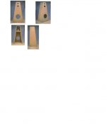
Thank You all for all your input and keeping this thread alive, as I will continue to post here and ask questions here through the progress of my speaker project . Hopefully I will be able to offer some tangible experiences to others of what I have learned, and give back insights that have been freely given to me. At any rate, my philosophy is this: research, experiment, think creatively and use the resources available. I firmly believe in the artisan approach, enhanced by technology, however, my ears will have the final say . There have been so many generous people here, some ideas of which, I have used, and some not. This is the beauty of the DIY community. Tinitus, I have taken some pictures of my unfinished partical board cabinet and am going to attempt to attach them here. Based on what you see here, along with what you have read in my posts, especially my posts on this thread, it is my hope to get some feedback from ANYONE who may be interested, as to the validity of my theories, perhaps offering tangible ways to enhance the project......Respectfully.............Omni.............
. There have been so many generous people here, some ideas of which, I have used, and some not. This is the beauty of the DIY community. Tinitus, I have taken some pictures of my unfinished partical board cabinet and am going to attempt to attach them here. Based on what you see here, along with what you have read in my posts, especially my posts on this thread, it is my hope to get some feedback from ANYONE who may be interested, as to the validity of my theories, perhaps offering tangible ways to enhance the project......Respectfully.............Omni.............Attachments
tinitus said:No Svante, it seems you are qualified
BUT - measurements or simulations - it seems to me that a speaker needs adjustments, no matter how good measurements are done
Problem with such tools, I think, are that one rely so much on them, that when measurements looks good the speaker is done and dry - and you simply cannot get yourself to do something that contradicts what your tool is telling you, no matter how good it sounds
But I guess a simulation program is good fore learning if you experiment - you can see right away what happens when you change values, but how it sound you may never know
Or will that be the next devellopment - to actually play the sound of the simulation
Yes, one should never rely on that measurements or simulations alone represents the whole truth. On the other hand, finding the best solution blindly, just by the ears is IMHO deemed to fail too. The best is when the two work hand in hand, you hear something, and find the cause of it with the help of measurements. It is when this happens that real progress is made.
Simulations are good for finding a first version that is reasonably close to a target, and they have the potential of being far more accurate than simple design formulas.
tinitus said:Hell, I would like a simulation program myself, just jealous
Is it allowed to ask here, how much it cost ?
Follow the Basta link and you will find the answer...
Svante, I am sorry you chose this thread here for a debate as to the virtues of your simulations package. I have started this thread in the hope that I may get some speaker building advice and help from those who can perhaps relate to my situation as I have outlined from the start. I have asked some very specific questions, seeking help, not all of which have been addressed yet, particularly by you. It is my hope that I can get input from people who have experienced the same frustrations that I am going through, and I would like the thread to grow as I move along this project, addressing the issues as they come up, during its' progress. I am not seeking technospeak, extolling the virtues of your wares, {WHICH I CANNOT AFFORD}, disguised as a sincere desire to help. Tinitus, and Sreten, along with a few others have attempted to keep this on course, Please, let us NOT digress. So, that being said, ANYONE interested in sharing ideas with me, please feel free to read the entire thread, and join me, as we journey through this project..................Respectfully............Omni
omni said:Svante, I am sorry you chose this thread here for a debate as to the virtues of your simulations package.
Sorry about that, I did not mean to turn the thread into advertising. Poor excuse, but I also write on another (swedish) forum where this would still be considered very much on-topic. My apologies.
I DO however think that the answer to your question lies in doing simulations rather than deciding if you should subtract the VC inductance or not. Neither of the cases will produce the exact response that the filter equations predict. With a simulation you will see what response you get.
Hi Omni, I am sure Svante is a nice and wise guy - but I am sure he didnt know the start of your project, where all this was debated and cleared, but this is maybe because you have made a new thread
You have made your choice, but no worry, it will work for you, and you know, sometimes one can know too much so everything gets impossible, or is not enough really
You have made your choice, but no worry, it will work for you, and you know, sometimes one can know too much so everything gets impossible, or is not enough really
Tinitus, I know all too well of the analysis paralysis that you speak of. It's one of my flaws in life and I appreciate your words on this forum. I will carry on with my project, however slowly, but also practice the art of letting go. Sometimes it's like a scientist who is at the threshold of performing the experiment which will either prove or disprove his theory. A bit of fear I guess, but also an excrutiating anticipation. What a paradox...........There is another guy who shared on this thread, I think it was Grant who also is endeavoring in a 3 way project, so if you are still out there, I hope things are going well.....................I will keep you posted, and when my boxes are complete, will post finished photos and talk about the sound. Though I may be using intiquated methods, I have done the work, enjoyed it and hope for excellent results.............Respectfully......Omni
- Status
- This old topic is closed. If you want to reopen this topic, contact a moderator using the "Report Post" button.
- Home
- Loudspeakers
- Multi-Way
- Crossover Inductor Determination