Hello, I am currently working on a crossfire tek504 (first repair).
The amp goes in and out of protect and also forces my power supply (ac to dc converter) to do the same when powered up.
I have read through the BCAE repair guide a few times to get some information as well. So as this is my first amp, I thought i'd dive right into metering the d718 and b688 transistor pairs.
Diode test mode for d718, attached to amp:
positive lead to B, negative to C and E-.55
negative lead to B, positive to C and E 1.2~+
Removed from amp:
positive lead to B, negative to C and E-.55
Nothing when reversed...
Similar readings for the b688 when in amp and when removed from amp
Confused, I removed all 4 transistors from one side (two of each type), and they all appear to meter within the acceptable .5-.7 range using diode test mode when outside and inside the amp, but only read 0 when outside the amp when reversing the leads.
I was expecting one of those to be bad, thus causing all of the others to read bad while installed on the board.
All of the d718 and b688 resistors are behaving the same way while installed in the amp board (I metered them all).
Thoughts on what to check next?
I don't see any visible damage/soot/scorch marks and I believe that this amp was dead shorted B+ to ground at some point (not sure, friends amp i'm learning on).
Thanks for the assistance.
JF
You need to state PRECISELY what the meter readings were. 0 isn't necessarily the same as 0.000. 'Nothing' is virtually meaningless.
What does the meter read with probes open (not in contact with anything but air)?
What does it read with the probes touching?
Post the readings for both ohms and diode-check.
What does the meter read with probes open (not in contact with anything but air)?
What does it read with the probes touching?
Post the readings for both ohms and diode-check.
Apologies, I'm used to saying nothing is no reading, or the meter doesn't change.
At stationary in diode and ohm mode, my meter reads as 1., bluepoint EEDM503B-model
Leads touching in diode and ohm mode read .000 after a few seconds of contact
I re-metered the D718 and B688 transistors that I removed from the amp:
D718
Removed from Board:
~.555 avg for the positive lead on B, negative lead on C and then E
Reversing the leads, meter reads no change, 1.
Mounted to Board:
~.555 avg for the positive lead on B, negative lead on C and then E
Transistor inside amp reads .620 for negative lead on B, positive lead on E
B688
Removed from Board:
~.555 avg for the negative lead on B, positive lead on C and then E
Reversing the leads, meter reads no change, 1.
Mounted to Board:
~.555 avg for the negative lead on B, positive lead on C and then E
Transistor inside amp reads .620 for positive lead on B, negative lead on E
Ohm mode:
Leads touching, ohm mode, reads .000
D718
Removed from Board
setting at 2M ohms, same leg testing as diode mode reads
1.689 for B C and 1.727 B E
Mounted in Board, B C reads .000 after a few seconds, 1. for B E
B688
Removed from Board
setting at 2M ohms, same leg testing as diode mode reads
1.402 B C and 1.484 B E
Mounted in Board reads 1.53, but continues to climb, after multiple seconds for B C
reads 1. for B to E, no meter change
There doesn't seem to be any shorted transistors.
Since you don't have an auto-ranging meter, you have to manually set it to the best range. When testing for leakage on a transistor out of the circuit, the highest resistance range is likely best. For testing in the board, you have to use a lower range because other components will skew readings. You cannot check for leakage with the transistors in the circuit.
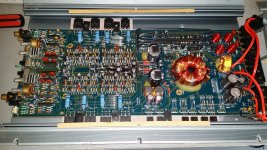
Post a good quality photo of the board.
Since you don't have an auto-ranging meter, you have to manually set it to the best range. When testing for leakage on a transistor out of the circuit, the highest resistance range is likely best. For testing in the board, you have to use a lower range because other components will skew readings. You cannot check for leakage with the transistors in the circuit.
Post a good quality photo of the board.
Ok...just remounted the board into the amp.
Not sure if this is progress or not but the amp no longer cycles green to red (doesn't trip protect on my PS either), but it is now flashing green every second or so.
Would you suggest I remove the remaining transistors as well, and test them all outside of the amp?
Remaining are the large (output) transistors on one side and what I am guessing are the smaller (power) transistors?
Last edited:
I am currently in the process of re-adding one channel at a time, up to 2 channels so far, no issues yet.
I do have another couple of questions though.
I can't seem to find specifics on what I should be looking for to test the transistors for leakage, as in, values and behavior wise?
I have been placing the leads on all legs in all combinations as suggested and recording the values, the seem to change but most of the time level out, but still change a bit while being metered in ohm mode. I am using the 20k and 200k modes, mostly the 200k mode.
Also, is there a way to discharge the amp?
I keep getting random sparks after the amp has been disconnected for multiple minutes, once when I was using diode mode on the meter, another when I was removing the heatsink clamps to take the board out of the amp.
On every test where you should get an open connection on diode check, you should get the same thing with the meter set to ohms. You cannot touch the metal part of the probes when you test for leakage.
You can short the rail caps. If you do it with a wire, it will make an intense spark and leave burn marks. If you do it through a resistor, it will be much less intense. I use my 2 ohm dummy load, generally. A 120v incandescent lamp will also work.
You can short the rail caps. If you do it with a wire, it will make an intense spark and leave burn marks. If you do it through a resistor, it will be much less intense. I use my 2 ohm dummy load, generally. A 120v incandescent lamp will also work.
How does one get at the positive side of these caps, they are under the board? I want to discharge the amp before removing it from the housing.
I've looked at and watched a large number of sites to construct something similar to what you mentioned, and a number of places mention using a 5 watt 470 ohm resistor.
Not sure if I have any resistors at that ohm level (470 seemed to be a happy medium for time to discharge and amperage output during contact of the resistor).
I know you mentioned using a light, but for safety reasons i'd prefer to use a resistor I can insulate.
So any suggestions on the ohm's needed for typical amp cap discharge and a way to discharge the caps that I can not reach?
You also mentioned a 2ohm dummy load...is this just attached to the speaker inputs on the amp, and how did you construct yours? I've seen various ways (most of which utilized some combination of resistors in mineral oil).
Thanks for the info so far.
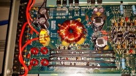
You can short the legs of the rectifiers. It appears that the rectifiers have the diodes facing to the right. If so, you can short the outer legs to discharge the caps.
An incandescent bulb in a small desk lamp is well insulated. Make sure that the switch is on. Touch the prongs of the plug to the points you want to short.
The 8 ohm 20 watt resistors from Radio Shack work well to discharge caps.
You can use virtually any resistor to discharge the caps, higher values will take longer but reduce the risk of making marks on the discharge points.
I use two 100 watt 2 ohm tubular ceramic resistors in series for a 4 ohm load. If I need a lower load, I parallel another pair with the first. To cool them, I use a fan to force air over and through their core.
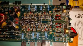
Confirm that the output transistors are in the correct locations.
Confirm that the two emitter resistors for that channel are within tolerance.
If those are the problem, you can compare resistance readings from the smaller transistors in the defective channel to the corresponding transistors in a working channel.
Confirm that the two emitter resistors for that channel are within tolerance.
If those are the problem, you can compare resistance readings from the smaller transistors in the defective channel to the corresponding transistors in a working channel.
My meter reads .1 at rest, and I 0.00 when touching.
If I read the colors correctly, those should be .5ohm resistors (the big blue ones are what I'm measuring) and I measured all of the resistors, but they are all connected to the board still.
So I removed one leg of a resistor from the board from the suspected bad channel and one from a good channel.
Measured at 200 ohm setting and both were in the .7 ~.8 range, suspected bad and good.
- Status
- This old topic is closed. If you want to reopen this topic, contact a moderator using the "Report Post" button.
- Home
- General Interest
- Car Audio
- Crossfire tek504 Repair