It can strongly advice investing in an oscilloscope. Either new or second hand. It's invaluable for any facet of DIY'ing. PSU ripple, signal comparison, troubleshooting, bass guitar output voltagesto name but a few.
Thanks to you, I discovered my audio interface does in fact have an oscilloscope! I've never needed it until now so I didn't care to look. Attached is a screen shot of my playing a rickenbacker 4003 with original passive single coil pickups. I am playing how I would normally play it live.
Attachments
This is with the pickup directly into the soundcard, right? Be careful when using a soundcard based scope especially on tube gear, the soundcard input needs to be buffered and voltage limited, otherwise you will kill it, typical soundcards can only handle <2Vrms or so.
It is an external audio interface, the motu mk3. It seems to have pretty large headroom, but I would still be cautious with it if hooking it up to any live circuitry. I was considering putting some zener diodes on the output, either just before the opamps or on the primary of an output transformer. I'm sure it would sound like a distortion pedal if the output went beyond the zener voltage, but at least it protects any equipment I'm feeding.
Just to be clear...the oscilloscope capture is me plugging directly into the interface. As of now I do not have any tube circuitry built.
Last edited:
I was chiming in to suggest you install a Zelscope or similar (they have saved my bacon more than once), when I see you already have one.
Now I'm busy (typical Saturday night and desperate customers waiting, no kidding) but later I'll post my simple add on safe Soundcard Scope adapter and the selectable attenuator to work inside tube amps.
Good luck.
Now I'm busy (typical Saturday night and desperate customers waiting, no kidding) but later I'll post my simple add on safe Soundcard Scope adapter and the selectable attenuator to work inside tube amps.
Good luck.
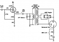
As promised, this is a very simple attenuator to go from murderous high voltages present in a Tube amp to the levels accepted by the fragile input of a PC soundcard (or an USB audio interface, which is about the same).
Build it in a plastic box, fully insulated, so there's no way you can touch anything inside and the 5 way rotary switch selector uses a plastic knob too.
From the box exit to the left 2 red/black wires with crocodile clips.
The red one is small, so you can clip it to a resistor or capacitor leg, a pot or jack terminal or a tube socket leg; the black/ground one must be a big strong badass one, so you clip it to chassis ground and it stays there.
To the right you exit with proper diameter shielded cable, and use either a mini stereo plug wired as indicated to go into a standard PC Line input (not the "mic" one) *or* a standard guitar plug, to go into the interface.
This attenuator pads the signal level selected to around 200mV , safe for Soundcards.
Diodes (1n4002 / 1N4148 / etc.) will clip any signal above 700 mV peak (about 400mV RMS).
The resistor values chosen are not "NASA quality" , this is not a precision Lab instrument but a practical solution, and values were chosen in roughly 5:1 steps .
An externally hosted image should be here but it was not working when we last tested it.
Hi Guys
The first CF could be eliminated entirely simply by reversing the order of the EQ and the gain control. As TUT6 describes, CF driven EQs tend to be rather limited in their range and dynamics.
The second CF should be self biased - just replace the series R from the preceding gain stage to a coupling cap, then get rid of the diode in series with the CF's grid-leak (such diodes a re a really bad idea).
As others have pointed out, the opamp circuit is not laid out properly. A TL072 is a poor choice for a line driver - better to use a 5532. Why not take the input to this circuit from the CF output since you are not providing separate levels for each anyway?
Overall, I see this as an Ampeg SVT pre with some bits re-ordered. It's not a great preamp but at least is much better than the associated power amp. The PA provides all the gain you need to go from instrument to speaker, as the PA input is protected by antiparallel diodes - so less than 700mV peak. A bass easily puts out that much signal if you bash the strings.
In light of the Ampeg-expected interface for the PA, it should be clear that you can eliminate the 68k-30k divider at the output level control if you want to drive any other standard PA input. Most PAs need 1-2V to achieve full output.
Supply voltage for the preamp effects headroom and linearity. Ampeg was nominally designing for clean tones, but also for muted treble tones as was the fashion of the day. As TUT3 details, playing through the SVT PA section alone yields a very muffled sound - no highs at all. Hard to get harmonics or a good slap-bass tone. Fender PAs are unlimited in this regard and much simpler to build.
You can make active EQ without coils.
Have fun
Kevin O'Connor
In an SS preamp, no big problem.You can make active EQ without coils.
In a tube preamp, with close to 300V power rails, the possible 300V PP signal available will be clipped to death by 30V PP max capability of +/-15V powered Op Amps.
That's why in tube amps Relays for switching (or LDR) and actual coils are still used instead of gyrators or CMOS/FET switches, typical tube level signals can't be handled by typical SS components.
In fact, most typical SS switches can handle even less: 15V PP .
Hi Guys
Jim, you might want to look at the history books, i.e., RDH, Wireless World, etc. The 1947 Baxandall active EQ used tubes and no coils, operating with typical tube preamp supply voltages. How is clipping more likely or more problematic with a 300V supply than with a 30V supply? Makes no sense that I can see.
Have you measured actual signals in a tube preamp? They are not all rail-to-rail as that would not actually happen due to the limitations of tubes, and would result in no dynamic change in the signal. If all tube stages worked that way tubes would have been abandoned soon after they were invented.
Ampeg built their circuits to be clean. They knew the source signal amplitude range and knew what the output power would be for a given amp design, then simply adjusted the gain in between to be appropriate, given tolerances of playing, tube aging, etc. Most amplifiers have a little more gain than needed to accommodate the worst case low-output pickup or light playing technique.
Your switching device comments must be related to another post, but again, you have not made a complete survey. There are many devices available to do switching that can handles 100s of volts. LDRs are rated at 100V peak, but mosfets go way over 1kV. Mosfets have to be used appropriately, however, as there are specific characteristics that limit their use, yet others that are rarely taken advantage of. There is more to switching than ICs.
Have you built any tube preamps yet? Or tried out any for your instrument? if not, then build a simple circuit first like a Fender pre - which is remarkably similar to other Ampeg preamps: two gain stages, EQ and level. Fender used their tone stack for the most part, although a Bassman model had active EQ which is how that model picked up its now useless CF, and Ampeg favoured passive Bax EQs.
The comment about feeding rail-to-rail signals from opamps suggests you want distortion. There is no need to have such large signals feeding into the tube preamp. Grid rectification does not sound musical.
Have fun
Kevin O'Connor
Last edited:
The second CF should be self biased - just replace the series R from the preceding gain stage to a coupling cap, then get rid of the diode in series with the CF's grid-leak (such diodes a re a really bad idea).
That is a DC coupled cathode follower. The diode is for longevity, and the lack of a capacitor is the feature of this stage.
Hi Guys
Yes, I know what DC coupling is. There is no need for the diode if you reduce the current through the follower. The follower is doing very little anyway so it can easily be dispensed with altogether. Were it driving the feedback loop or one of the long output cables, it would serve some purpose. At the moment, it just increases tube count. Ampeg used a single-triode bottle to implement it, but that was when you could get such things cheaply.
The reason DC coupled followers need protection is that they can latch up during start-up. The grid goes positive before the cathode is emitting electrons and the tube ends up saturated. Not surprisingly, if the cathode resistor is higher in value this latch up never happens.
If you really need the follower and also really want the attenuation to the output level control, you can simply split the cathode resistor and take the signal from the tap. This would seem appropriate given the comments above about reducing component count. On the other hand, this solution requires a higher value cap than placing the attenuator after it.
Have fun
Kevin O'Connor
When I studied Engineering those were not "History Books" but reference books on the University's library shelves.Hi Guys
Jim, you might want to look at the history books, i.e., RDH, Wireless World, etc. The 1947 Baxandall active EQ used tubes and no coils, operating with typical tube preamp supply voltages.
Back to the thread, here we are adjusting parts values of the Bass/Treble control (classic Ampeg: a passive James control), not replacing it by a Baxandall one.
But when you mentioned "actives", I was talking specifically about the Middle control, so much so that the point was analyzing it and explaining the OP why it would work poorly when on Boost.
And it does involve coils.
Your comment about using Active Filters implies the use of gyrators, which are commonly made around Op Amps or transistors.
Yes, gyrators *may* be made with tubes, but I doubt anybody will prefer to drill a big hole, mount a socket, supply extra filament and plug a tube there just to save on using a coil.
I didn't say that, (please reread my comment), *but* a strong signal which lives happily inside a tube preamp (with a 300V rail) can NOT be handled by the low voltage part, specially a +/-15V (=30V end to end) Op Amp.How is clipping more likely or more problematic with a 300V supply than with a 30V supply? Makes no sense that I can see.
So although an Op Amp is a great building block which has replaced coils in equalizers, it simply can't cope here.
You betHave you measured actual signals in a tube preamp?
And designed, built and sold them since 1969 .
No, not *all*, didn't say that either, although you should be aware that rail to rail signals are very common in Musical Instrument amplifiers.They are not all rail-to-rail as that would not actually happen due to the limitations of tubes, and would result in no dynamic change in the signal.
That's called "Clipping" or "distorsion" and in fact is something sought after, designs often *try* to clip or distort.
And that "no dynamic change in the signal" you mention is called "sustain" or "distortion" or "compression" and is also sought after.
You added the "all" qualification, not me.If all tube stages worked that way tubes would have been abandoned soon after they were invented.
And as of "abandoning tubes because they are dirty" ..... have a look around.
Well, agree that was the idea behind the "old" Ampegs of the Fifties, the era when they were used by Accordion and Jazz players, but when the SVT (and its cousins, the V4, etc.) were designed, it was the Woodstock era and beyond.Ampeg built their circuits to be clean. They knew the source signal amplitude range and knew what the output power would be for a given amp design, then simply adjusted the gain in between to be appropriate, given tolerances of playing, tube aging, etc.
Music (and the World) had changed a lot.
True.Most amplifiers have a little more gain than needed to accommodate the worst case low-output pickup or light playing technique.
Not necessarily, I added them to the discussion to show another example of a modern practical and very good solution, used everywhere, which can't handle what's routinely inside a Tube preamp.Your switching device comments must be related to another post,
But this is not a surveybut again, you have not made a complete survey. There are many devices available to do switching that can handles 100s of volts. LDRs are rated at 100V peak, but mosfets go way over 1kV. Mosfets have to be used appropriately, however, as there are specific characteristics that limit their use, yet others that are rarely taken advantage of. There is more to switching than ICs.
Here we are trying to help a fellow Forum Member build a better preamp, please read the thread title.
The idea is to suggest practical and focused solutions, not to write a Book.
When I started, there was nothing elseHave you built any tube preamps yet?
Would designing, building and successfully selling Tube/Transistor/Op Amp/Fet/MosFet M.I. equipment for the last 43 years count?
Or having built and sold more than 10000? (over ten thousand, not a typo)
Unfortunately, I'm a boring Engineer, almost retired now, not a cool Musician, and I can play no instrument.Or tried out any for your instrument?
Yes, I have a few "shop instruments" for Musicians to try my amps if they can't bring their own, but can't play any to save my life.
Nice suggestion, but you arrive 43 years lateif not, then build a simple circuit first like a Fender pre -
The first tube amp I built (February 1969) was a Gibson GA5 clone (1 x 12AX7 + 1 x 6V6).
A couple months later I built a 50W Blackface Bassman.
By the end of the year I was building and selling simplified Twin Reverb based heads driving 8 x 10" speakers or 4 x 12" ; we had no access to high power speakers.
So much so, that later I had to design and build my own speakers, which I also sell to other builders.
By 1972 I was designing, building and selling 200W RMS SS power amps and stackable 4 channel mixers.
Way back then, it was state of the art PA equipment for working Bands.
You seem to forget that the *order* of those elements makes a BIG difference.which is remarkably similar to other Ampeg preamps: two gain stages, EQ and level.
That's why Fender/Marshall/VOX sound so different yet there are examples of all 3 with the elements you mention.
There are basically 2 very different "Fender Tone Stacks"; although the labels (Treble/Mid/Bass) may be the same, I mean the Tweed ones and the Blackface/Silverface ones, so please make clear which one are you talking about, not the same.Fender used their tone stack for the most part,
I'd *love* to see that "active eq", never heard.although a Bassman model had active EQ which is how that model picked up its now useless CF,
Do you think the CF is useless?
I wonder why it's so popular.
There's not such a thing as a "Passive Baxandall", maybe you refer to a passive "James" EQ .... because that's what Ampeg uses.and Ampeg favoured passive Bax EQs.
The comment about feeding rail-to-rail signals from opamps suggests you want distortion. There is no need to have such large signals feeding into the tube preamp. Grid rectification does not sound musical.
I didn't say so.
I was *comparing* tube signal level capability to Op Amp capability, and the mention of respective rail to rail voltages, was to emphasize the HUGE 10:1 difference in real, practical terms, that anybody can see.
I am having lots of it, thanksHave fun

OK, sorry.
The idea is to help the OP, at least that's what I tried to do all along with practical, useful suggestions.
Don't understand why this turned into a ******* contest, with really undeserved despective comments such as
Thanks.
The idea is to help the OP, at least that's what I tried to do all along with practical, useful suggestions.
Don't understand why this turned into a ******* contest, with really undeserved despective comments such as
, or"Have you built any tube preamps yet?"
"if not, then build a simple circuit first like a Fender pre"
Thanks.
gents, you are disrespecting a member's thread
moderation
No worries here, I'm getting a lot from this thread.
Hi Guys
Frankly, asking someone if they've built something is not offensive, rather a way to find out what experience they have. Many of the comments made suggested a distinct lack of experience or understanding about how these circuits function and/or how they are typically used. As a point of interest, the SVT followed the original Ampeg philosophy of design: loud, clean headroom. Things had just gotten loud enough by the 1970s to warrant having a 300W+ amp. The "intended" users applied the amp just as designed, where the players in the evolving heavy rock and blues forms were pushing amps to clipping. Ampeg's philosophy was very similar to Leo Fender's with respect to intended use of their products.
With respect to the original poster's circuit: In moving the end of the feedback path from the CF output to the plate of the first stage of the EQ block, you've bypassed the second gain stage and lost all of the "power" of the feedback loop. The amount of boost and cut is severely reduced this way. In the context of the Ampeg circuit, the CF was useful in that it drove the feedback path and the output of the block with a low impedance. This is necessary given that in their circuit, when the mid pot is panned all the way to one end only 620R separates the coil to ground from the EQ block output. There is also a second loop that provides broadband gain.
What you have instead is a poor version of the EQ used in the Fender 200W bass amp. That circuit looks like a concertina splitter with the main output taken from the plate. The EQ pots straddle the plate output and cathode output with their wipers tied to ground through LRCs. The stage becomes a gain stage when the pot is swept to one end - at least for a given frequency range - and the signal is passively cut at the other end. This EQ is set up as a 6-band EQ including the presence control.
How much warmth a given circuit adds is up to the individual player to assess. One or two free-running stages adds distinct tube colour. The enhanced circuits, such as SRPP or circuits with feedback loops, tend to lose some of their tubiness but have their aesthetic appeal mostly from a technical view. In this regard, it is highly relevant if the original poster has built or tried any of these simpler things, or is he just launching directly into the technically interesting circuit?
As I said above, the Ampeg PA has a seriously limited frequency response that squashes the dynamics of the preamp tone. Building just the preamp will result in a brighter tone than you may be expecting. Also keep in mind that most MI speakers are woofers with very poor treble response. Speakers have a huge influence over the final sound. Going direct into a sound card or mixer will require a bit of EQing to have a tone similar to a miked speaker cabinet and complete amp. Fortunately, achieving this in the small signal domain is relatively cheap and easy.
TUT3 provides a history of the Bassman and SVT circuit evolutions with easy to build final forms that use off-the-shelf transformers and parts.
Have fun
Kevin O'Connor
Last edited:
Hi Guys
It may be that the passive form is the James and the active form is Baxandall. The similarity of the forms is unmistakable and I've always seen both referred to as bax - whether that was correct or not - and have simply done so myself for decades. Either is very useful and provides a flat frequency resposnse at the mid settings of the controls, unlike any variant of "tone stack".
I use "EQ" to refer to any equaliation block. Maybe for some "EQ" implies "graphic EQ" with the implied usual gyrator circuitry? That would just be one's own experience and each of us has our own unique experience and thus a unique interpretation of the world.
I was mistaken when I referred to the Bassman with active EQ. That model had feedback for active mixing but drove passive EQ. It was an experiment that did not stay in production very long, with the FB loop disappearing but the CF remained, killing tone for every copy built thereafter - including Marshalls et al. TUT6 explains this in detail. As detailed, a CF when driving passive EQ is pretty much useless. CFs otherwise have many uses.
Active EQ is not a panacea for everyone. It has its pros and cons. In the context of a tube circuit, the dynamic loading variations on a free running gain stage made by passive EQ circuits makes the overall effect much more lively. Plate-driven EQ tends to "seem to do more" than CF driven EQ - not just my opinion but that of thousands of players. Retaining the CF or not depends on the goals set for the circuit and what the particular builder _believes_ to be relevant to achieving the goal. He may set up hurdles without knowing it, but those details are important to him and one can work around any tonal bottleneck to get to the final goal.
With any project, you have to set an initial goal. Try out ideas you think will get you there. Assess how close to the goal or far away from it you are and then proceed with refinement or begin with another circuit altogether. Each project has its own journey.
Have fun
Kevin O'Connor
Hi Guys
With respect to using single or multiple PTs, I think it comes down to economics. If you are building a one-off and just "testing" and idea, then use what is at hand. You may end up with separate PTs for plate, heater, aux. If this is something to be put into production, you choose between an off-the-shelf piece that might be close to your needs and adapting the circuit to use it, or you get a custom PT - not expensive, actually - or you go with multiple PTs because that is what is cheapest to you on an incremental basis. The latter part just means that if you can buy three standard pieces one at a time each, it is certainly less of an investment than having to buy a minimum quantity for a custom part. Only a few transformer makers impose minimum quantities nor minimum order values.
The SVT and V9 were unique in the MI world, in being on the cusp of truly requiring a standby switch. They implemented this simply by splitting the heater support from everything else, so the standby switch activates the plate/bias PT and the mains switch activates the heater PT and powers the s/b. So, there you see multiple PTs used in a practical way.
The use of separate PTs for each supply in a split rail is entirely wasteful of the PT. A centertapped device will provide power to both rails. The load in most cases is a class-AB amp that pulls heavy current from rail at a time, so smaller PTs can be used this way. With a separate PT for each rail, each PT has to be rated for the heavy load, effectively doubling the VA rating and cost of the supply but not doubling the current delivery. Where the latter comes into its own is for bridge-wired amps.
As others have mentioned, regulation is relevant or not. Hard regulation of all voltages allows one to commit many layout sins without serious detriment. Regulator outputs should be well-filtered to reduce the frequency response effects of the regulator itself. In this regard, active hum filters are a much better alternative.
Heaters do not need regulation nor do they need DCing even in a high gain preamp provided they are tied to a DC standoff. This provides 30db of heater hum infiltration - the same as DCing. In a preamp comprised of tubes that can have their heaters wired for 12V, this provides a distinct noise advantage with respect to wiring. For the 12A_7 family, 12V wiring keeps all the heater wiring to one side of the tube, so no grid wire has to cross the heater lines (depending on how the tubes are oriented). The lower current of this wiring also makes regulation simpler if you decide to implement that.
Have fun
Kevin O'Connor
- Status
- This old topic is closed. If you want to reopen this topic, contact a moderator using the "Report Post" button.
- Home
- Live Sound
- Instruments and Amps
- Critique my preamp design