Star connection.
From what I see on your diagram there are three things that should be done differently or at least tried:
1) Supposing the input RCA is isolated from chassis, as it should be, the earth should go to the star, not to the amp. You can use a shield or twisted pair soldered just at one end to "signal ground". That can be one potential hum source. That should explain why you still have hum with CD disconnected. The "signal ground" at every amp should go to the star, of course.
2) The input RCA ground (green wire) should not go to chassis but to the star. A separate wire should go from star to chassis. Do not connect the AC ground (green/yellow wire) directly to chassis, as it should also go to the star if you use it all. See if anything changes when you connect it, like hum.
3) A star point is a POINT, not a square plate. Why don't you try joining all grounds that should go to a star go to a SINGLE point, perhaps a screw that is isolated from chassis where all wires are bolted to?
Points 1 and 2 should be modified in your arrangement, starting by 1. Then see if 3 improves things further. In my opinion it should.
If you don't get it I can make a new drawing.
Be aware that at maximum volume you may listen to a slight ripple.
Carlos
Re: Star connection.
1) Input RCA is not isolated from chassis at the moment so this should be done. Did I understand right?
I use shielded cable from input RCA to amplifier, so where should I connect that cable shield(outer conductor)? Directly to star point? But why in Elektor that RCA shield (outer conductor) is connected directly to amplifier board?
2) I will answer later to this
3) and this
I'm stupid or something but..... PLEASE... can you make drawing. I will be very grateful")
carlmart said:From what I see on your diagram there are three things that should be done differently or at least tried:
1) Supposing the input RCA is isolated from chassis, as it should be, the earth should go to the star, not to the amp. You can use a shield or twisted pair soldered just at one end to "signal ground". That can be one potential hum source. That should explain why you still have hum with CD disconnected. The "signal ground" at every amp should go to the star, of course.
2) The input RCA ground (green wire) should not go to chassis but to the star. A separate wire should go from star to chassis. Do not connect the AC ground (green/yellow wire) directly to chassis, as it should also go to the star if you use it all. See if anything changes when you connect it, like hum.
3) A star point is a POINT, not a square plate. Why don't you try joining all grounds that should go to a star go to a SINGLE point, perhaps a screw that is isolated from chassis where all wires are bolted to?
Points 1 and 2 should be modified in your arrangement, starting by 1. Then see if 3 improves things further. In my opinion it should.
If you don't get it I can make a new drawing.
Be aware that at maximum volume you may listen to a slight ripple.
Carlos
1) Input RCA is not isolated from chassis at the moment so this should be done. Did I understand right?
I use shielded cable from input RCA to amplifier, so where should I connect that cable shield(outer conductor)? Directly to star point? But why in Elektor that RCA shield (outer conductor) is connected directly to amplifier board?
2) I will answer later to this
3) and this
I'm stupid or something but..... PLEASE... can you make drawing. I will be very grateful
Re: Re: Star connection.
1) Yes, you did. Input RCAs should isolated from chassis where they are located. Most good connectors already have a Teflon isolator included. If your grounds are separated in your amp pcb, then you should have a "signal ground" track that should go separately to the star. Solder the shield only at that end. My preference is for twisted pair for this. You can put a 0.01uF ceramic cap between input ground and chassis ground right at the connector.
2) Put star point anywhere, preferably away from transformer, with bolt isolated from chassis. You can then add a cable to chassis. Sometimes using a small resistor in series with DC chassis wire can be tried, as well as on AC chassis wire to see which is more silent.
3) No, don't place it too much away from capacitors. In fact this star point should be as equidistant as possible from all grounds. That is if there's a 20cm distance between main capacitors and amp, put your star at 10cm. Wire shouldn't be too thin on the capacitors ground, something like 18 gauge should do.
Carlos
Eccu said:
1) Input RCA is not isolated from chassis at the moment so this should be done. Did I understand right?
I use shielded cable from input RCA to amplifier, so where should I connect that cable shield(outer conductor)? Directly to star point? But why in Elektor that RCA shield (outer conductor) is connected directly to amplifier board?
2) Can I make that starpoint with some kind bolt through base plate?
3) By the way.... can that starpoint be about 20-30cm (8-14 inch) away from main capasitors? Is there any disadvantages?
1) Yes, you did. Input RCAs should isolated from chassis where they are located. Most good connectors already have a Teflon isolator included. If your grounds are separated in your amp pcb, then you should have a "signal ground" track that should go separately to the star. Solder the shield only at that end. My preference is for twisted pair for this. You can put a 0.01uF ceramic cap between input ground and chassis ground right at the connector.
2) Put star point anywhere, preferably away from transformer, with bolt isolated from chassis. You can then add a cable to chassis. Sometimes using a small resistor in series with DC chassis wire can be tried, as well as on AC chassis wire to see which is more silent.
3) No, don't place it too much away from capacitors. In fact this star point should be as equidistant as possible from all grounds. That is if there's a 20cm distance between main capacitors and amp, put your star at 10cm. Wire shouldn't be too thin on the capacitors ground, something like 18 gauge should do.
Carlos
Re: Re: Star connection.
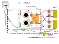
An image is worth 1000 words, they say. Let's hope this one does.
Carlos
Eccu said:
I'm stupid or something but..... PLEASE... can you make drawing. I will be very grateful
An image is worth 1000 words, they say. Let's hope this one does.
Carlos
Attachments
Very big thanks Calrmart!
I will test that on next week, because I have some other job for weekend. I will tell result when I have been tried that.
But still one question about that picture:
Is that resistor placed to wire from starpoint to chassis? And how big it is?
Is that safe, because if that resistor fails then there is change to get AC voltage to chassis -> possible to get electric shock? Am I right?
There is still one difficult task. There is not enough room for starpoint in my amplifer case (in PSU part). In amplifier part there is some room, but about 20cm away from main capasitors.
Eccu said:
Is that resistor placed to wire from starpoint to chassis? And how big it is?
Is that safe, because if that resistor fails then there is change to get AC voltage to chassis -> possible to get electric shock? Am I right?
There is still one difficult task. There is not enough room for starpoint in my amplifer case (in PSU part). In amplifier part there is some room, but about 20cm away from main capasitors.
Resistor can be 10 ohms/5w type. You can also leave that AC ground not connected to chassis, floating. That is what I do.
In any case try it connected straight, with resistor and unconnected and see which provides less hum. If all are the same use the one you prefer or feel safer with.
20cm is not so far away. Just check you are away from transformer. Speakers should be connected to this star too.
Carlos
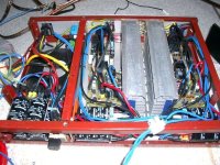
This is one quick shot from my bare amplifier. Horrible wire mess. 
You see that there is quite much "recycled" stuff. Allmost all mechanics was recycled.
Can I place that starpoint to front of heatsinks? It is only free space at the moment.
Transformer is placed out of case during hum -testing.
Picture is little overexposed or so.
You see that there is quite much "recycled" stuff. Allmost all mechanics was recycled.
Can I place that starpoint to front of heatsinks? It is only free space at the moment.
Transformer is placed out of case during hum -testing.
Picture is little overexposed or so.
Attachments
Eccu said:
Can I place that starpoint to front of heatsinks? It is only free space at the moment.
Yes, that should be fine. Just don't let any hot metal touch the star wires.
Carlos
http://www.gmweb.btinternet.co.uk/jlhearthing.htm
I made my earthing like this link advise. So is this earthing-PSU schematic incorrect?
I made my earthing like this link advise. So is this earthing-PSU schematic incorrect?
Eccu said:http://www.gmweb.btinternet.co.uk/jlhearthing.htm
I made my earthing like this link advise. So is this earthing-PSU schematic incorrect?
They have a star too, with two differences:
1) The AC earth is connected to a separate point. Though they suggest it can be connected to the star too. The audio ground should never be connected to it though IMHO.
2) They join the capacitors and connect the transformer middle point to it though, then going to the star. You may try and see if that improves things, but I don't think it will.
In any case, as you see, earthing is not something everybody agrees one. So you will have to try and see which works better for you.
Carlos
- Status
- This old topic is closed. If you want to reopen this topic, contact a moderator using the "Report Post" button.
- Home
- Amplifiers
- Solid State
- Crescendo protection circuit?