ADCR = Amplified Double Chamber Reflex
I think a good name for this type of design would be ADCR = Amplified Double Chamber Reflex, which is basically what it is
Here's an DCR that i did today with the time i had, with the intention of taking it further at some point by adding on the A
*
18 Sound 18NLW9600
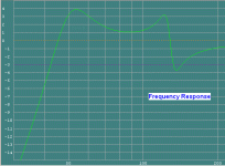
45Hz - 130Hz + or - 2dB
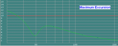
No excursion problems
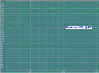
Full 1800W AES Power down to 40Hz
Box =
Vol 1 = 120 L - Port 1 = 150mm Diam x 380mm L
Vol 2 = 60 L - Port 2 = 150mm Diam x 200mm L
Internal Port 3 = 150mm Diam x 50mm L
3 x Round Ports
*
Looks ok so far in all respects i believe, and adding on the A should "hopefully" GAIN further benefits
As regards modelling in AkAbak/HornResp etc, i think "possibly" just treating the back ported sections as one entity, as is usually done in TscH, but dailing in the extra gain etc, "might" work ? Be very interesting to see how this all pans out
TscH = Tapped so called Horns ! Why, because i don't think the Horn term is really justified. That doesn't mean that TH designs havn't got merit, because indeed they do, and then some
*
@ tb46
Yeah a PP variant design could work with the right parameters etc. I just tried altering my DCR design i've posted to a PP, and it would require a bit more tinkering, but doable
*
DCR design, not PP
Attachments
Last edited:
As in (I would just love for one of the AkAbak experts to stick this one into AkAbak) :
Regards,
I'd do it if you provide a fully dimensioned and scaled drawing. Otherwise I'd have to print the PDF in large scale and go over it with a ruler... I've done it before, and come to the conclusion that life is too short to do it that way.
Hi Don,
I'll see if I can find the time tonight to put the additional dimensions into the doodle, it should not be too much work. It might just be interesting to see how bad it turned out, as this is just a concept doodle without any computation. I would be nice to have a generic AkAbak simulation, that way we could see if this can be made to work.
Regards,
Problem ? - Suggestion !
@ tb46
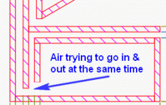
Hi, i applaud your efforts, but think there "may" be problems, as i've shown. A similar looking problem is also in old skool junkie's first picture.
I think my suggestion would better accomplish the design goals, of your's & old skool junkie, and could be applicable to both ADCR = "Amplified Double Chamber Reflex" designs, with or without PP.
Attachments
Last edited:
Design
OK.
Me too, so i hope people are able to expand on the concept, & also see how it shapes up in AkAbak/HornResp etc, as some have intimated they might be able to
OK, & a nice sketchup
Regards
Originally Posted by tb46
I don't have any design goals in this thread.
OK.
I just find it generally interesting,
Me too, so i hope people are able to expand on the concept, & also see how it shapes up in AkAbak/HornResp etc, as some have intimated they might be able to
and answered a question of the OP's with a suggestion.
OK, & a nice sketchup
Regards
Very interesting take on the port differentiation (<spelling?). I never thought about the air conflicting at that particular junction. I'm just now sitting down to re-design the enclosure, I'll report back ASAP for critique. Thanks again everybody!
tb46, thank you for going the extra mile for the sketchup(s)!
tb46, thank you for going the extra mile for the sketchup(s)!
Hi Zero D and old skool junkie,
Zero D: Your idea might well simplify the interactions in the second chamber. To make the general change you suggest, and still maintain about the same length for Duct_2 it might be better to leave Duct_2 pretty much alone, and change the position of Duct_3 (see attached sketch). By the way, I don't think this can be modelled in Hornresp.
old skool junkie: please, take a look at the enclosed attempt to integrate Zero D's suggestion. I also changed the position of the PPSL option a bit.
Regards,
Attachments
Last edited:
for some reason i can't help think the crossover port should be tuned higher than the horn port. say the horn port (tuned to 24hz) and the crossover port (tuned to 35hz) to the resonator chamber and passband port (tuned to 40hz). or something along those lines...
although the passband port will need to be able to move a lot of air without chuffing...
maybe make the second chamber into a horn instead of a bandpass.
edit: after more thought... a hybrid Sachiko/bandpass box is odd... without the speaker being incased in the box (as in a true bandpass box), the higher tuned port will unload before the lower tuned port couples with the driver
Last edited:
Designs Plus
Thanks.
Yes, i believe there would interference.
Ok, great, pleasure
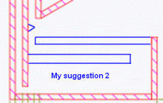
Have a look at my revised drawing below = My suggestion 2
Yes i think it would.
Indeed, thanks, and having had more time to ponder over it, i've included a revised drawing below = My suggestion 2. The idea behind it is to make both port outputs as close as possible to each other, and also nearer to the direct output from the driver/s. The reason being, to attempt to have a closely coupled combined output, sort of hybrid of DCR & TscH, as i mentioned earlier.
I know what you mean, but hopefully "someone" may make it happen. Also the nice folks at Hornresp & AkAbak etc, might tinker with their code to enable these designs to be modelled
@
Hi, just seen your post, so i'll give it some consideration
*
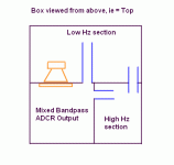
I'm also posting/proposing a different design, which is one i referred to earlier. This is an ADCR, again a hybrid, which "might" encompass the benefits of several designs in one.
The direct driver/s output chamber could be made more horn shaped. And once again as above, "both port outputs as close as possible to each other, and also nearer to the direct output from the driver/s"
Originally Posted by old skool junkie
Very interesting take on the port differentiation (<spelling?).
Thanks.
I never thought about the air conflicting at that particular junction.
Yes, i believe there would interference.
I'm just now sitting down to re-design the enclosure, I'll report back ASAP for critique. Thanks again everybody!
Ok, great, pleasure
Have a look at my revised drawing below = My suggestion 2
Originally Posted by tb46
Your idea might well simplify the interactions in the second chamber.
Yes i think it would.
To make the general change you suggest, and still maintain about the same length for Duct_2 it might be better to leave Duct_2 pretty much alone, and change the position of Duct_3 (see attached sketch).
Indeed, thanks, and having had more time to ponder over it, i've included a revised drawing below = My suggestion 2. The idea behind it is to make both port outputs as close as possible to each other, and also nearer to the direct output from the driver/s. The reason being, to attempt to have a closely coupled combined output, sort of hybrid of DCR & TscH, as i mentioned earlier.
By the way, I don't think this can be modelled in Hornresp.
I know what you mean, but hopefully "someone" may make it happen. Also the nice folks at Hornresp & AkAbak etc, might tinker with their code to enable these designs to be modelled
@
revboden
Hi, just seen your post, so i'll give it some consideration
*
I'm also posting/proposing a different design, which is one i referred to earlier. This is an ADCR, again a hybrid, which "might" encompass the benefits of several designs in one.
The direct driver/s output chamber could be made more horn shaped. And once again as above, "both port outputs as close as possible to each other, and also nearer to the direct output from the driver/s"
Attachments
Mod_2
Hi Zero D,
Your suggestion from Post #31 would combine two ports, so maybe terminate Duct_3 half-way up the horn? To follow your original idea the junction of the two ports in the upper chamber should be pulled apart too.
Regards,
Hi Zero D,
Your suggestion from Post #31 would combine two ports, so maybe terminate Duct_3 half-way up the horn? To follow your original idea the junction of the two ports in the upper chamber should be pulled apart too.
Regards,
Attachments
Last edited:
Ok. I'm seeing double (no sleep) so I'm gonna hit the sheets. Here's what I've got done so far:
I've re-designed it from the ground up, with all of the ideas you guys pointed out in effect (I hope). Oh, and this is only the bottom part ...
I've attempted to create a 6th order for these, incorporating the "dual chamber ported system" on BOTH sides of the woofer. Should be interesting. As always, input/critique is greatly appreciated
*Note: I cannot and will not take credit for this particular idea entirely. The exact design: mine 100%. But the idea: was brought to my attention by a close friend of mine (Justin). In fact, I credit most of my elaborate box designs to him.
An externally hosted image should be here but it was not working when we last tested it.
I've re-designed it from the ground up, with all of the ideas you guys pointed out in effect (I hope). Oh, and this is only the bottom part ...
I've attempted to create a 6th order for these, incorporating the "dual chamber ported system" on BOTH sides of the woofer. Should be interesting. As always, input/critique is greatly appreciated
*Note: I cannot and will not take credit for this particular idea entirely. The exact design: mine 100%. But the idea: was brought to my attention by a close friend of mine (Justin). In fact, I credit most of my elaborate box designs to him.
Hi Don,
This is what I came up with, let me know if you need anything else:
Regards,
Thanks, Oliver. I'll get on to it.
OK, here's a first cut.
Notes:
- I couldn't find the parameters for the Kove drivers. I used the parameters for some CSS 6.5" drivers. Just replace the values with the correct ones.
- I arranged the script so that you can "disconnect" the extra ports and box, leaving a fairly standard tapped horn configuration.
- Initial results aren't very promising, the additional ports and volume seem to hinder more than help. Maybe using the correct driver values and adjusting various dimensions will help.
- You can use the "Inspect" functions to examine the airflow and pressure etc in various parts of the box to figure out the contribution each part is making.
To use:
- Start AkAbak.
- File --> New
- Delete the "System" line, leaving a blank script.
- Cut'n'paste in the code from below.
- Sum --> Acoustic Pressure... (or press F5)
- OK
Since this is a bass speaker, on the Acoustic Pressure dialog you might try changing the frequency range from 20Hz-20KHz to 10Hz-1KHz.
(If, instead of the Acoustic Pressure dialog, you get a black line on the script, it means there's a typo somewhere near the highlighted line.)
Code:
| "Crazy box style" mod_2, Kove 6.5 inch drivers
| Couldn't find Kove T-S parameters, used CSS SDX7

Def_Const
{
box_w = 40.84e-2; | Width of enclosure (cm)
}

|===================================================

|Network node numbers for this system:
|
|      0-Voltage-1
|                |
|           +--Drive1--+
|           |    |    21--Manifold--+
|           +--Drive2--+            |
|           |                       |
|Rear box--11--Duct_1--12--Horn_1--13--Horn_2--14--Radiator
|           |
|           +--Duct_2--31--Box2_1--32--Box2_2--0
|                                   |
|                                   +--Duct_3--33--Radiator

|==================================================

Def_Driver  'CSS SDX7'
  SD=128cm2   |Piston
  fs=34Hz
  Mms=21.9g
  Qms=2.2
  Qes=0.41
  Re=6.4ohm
  Le=0.75mH
  ExpoLe=0.618


System 'System'

  Driver Def='CSS SDX7' 'Driver1'
    Node=1=0=11=21

  Driver Def='CSS SDX7' 'Driver2'
    Node=1=0=11=21

  Duct 'Driver Manifold'
    Node=21=13
    SD=322cm2
    Len=23.1cm

  Enclosure 'Box Behind Drivers'
    Node=11
    Vb=38.775L
    Lb={box_w}

  Duct 'Duct_1'
    Node=11=12
    SD=108.2cm2
    Len=57.7cm

  Waveguide 'Horn Part 1'
    Node=12=13
    STh=108.2cm2
    SMo={18.1e-2 * box_w}
    Len=28.6cm
    Conical

   Waveguide 'Horn Part 2'
    Node=13=14
    STh={18.1e-2 * box_w}
    SMo={24.9e-2 * box_w}
    Len=11.7cm
    Conical

  Radiator 'Horn Mouth'
    Def='Horn Part 2'
    Node=14
    x=0  y=0  z=0  HAngle=0  VAngle=0

| Un-comment the word "Off" to disconnect the extra ports
| and the second box, leaving a standard tapped horn style.
| Off

  Duct 'Duct_2'
    Node=11=31
    SD=108cm2
    Len=80.3cm

  Duct 'Box 2 Part 1'
    Node=31=32
    SD=584cm2
    Len=14cm

  Duct 'Box 2 Part 2'
    Node=32=0
    SD=697cm2
    Len=23.5cm

  Duct 'Duct_3'
    Node=32=33
    SD=77.3cm2
    Len=58.3cm

  Radiator 'Port Mouth'
    Def='Duct_3'
    Node=33
x=0 y=0 z=0 HAngle=0 VAngle=0AkAbak Model
Hi Don,
That looks great. This may be the first time that there is a model for a Weems style Dual Chamber Reflex w/ a djk PPSL manifold, and a short horn. This is really neat, and should be useful to anybody trying to build something like this. Beats cutting around in the dark.
One more question: how do you add a passive crossover filter, e.g.: LC 2nd order low pass to this model?
Regards,
The simplest way is to add an inductor and capacitor to the model. The inductor connects between the input (node 1) and the drivers. The capacitor goes between the drivers and ground.
Like this:
You have to figure out what values you want for the components.
AkAbak will also work "from first principles". You can use the "Filter" tools to define your filter (crossover frequency, order etc) and AkAbak will apply it so you can see how it works and adjust it. When you are satisfied, it will help you to convert the definition to actual component values for either passive or active crossover. I won't describe the process here as it is (relatively) complex, and is described with worked examples in AkAbak's tutorial exercises manual and the example scripts included with the program.
Like this:
Code:
  Coil 'L1'
    Node=1=2
    L=10mH
    Rs=0.1ohm

  Capacitor 'C1'
    Node=2=0
    C=100uF

  Driver Def='CSS SDX7' 'Driver1'
    Node=2=0=11=21

  Driver Def='CSS SDX7' 'Driver2'
    Node=2=0=11=21
You have to figure out what values you want for the components.
AkAbak will also work "from first principles". You can use the "Filter" tools to define your filter (crossover frequency, order etc) and AkAbak will apply it so you can see how it works and adjust it. When you are satisfied, it will help you to convert the definition to actual component values for either passive or active crossover. I won't describe the process here as it is (relatively) complex, and is described with worked examples in AkAbak's tutorial exercises manual and the example scripts included with the program.
Actually, the 'PPSL" part of the box is not required. You can achieve the same results by simply mounting the drivers on the horn panel. There's just enough room to mount them across the width of the horn, in the same position as the mouth of the PPSL manifold.
You can simulate this by connecting the drivers diectly to the horn, and commenting out the manifold, so it looks like this:
When you run this, you get a response almost identical to the original and it's much easier to build.
If you decide to build it this way, remember to adjust the dimensions to compensate for the volume of the missing manifold.
In my opinion, the only reason to use a PPSL type manifold would be to fit drivers that would otherwise be too large for the baffle. You are effectively folding the baffle into the enclosure, so the enclosure has to be larger to maintain the same internal volume. There is no free lunch...
You can simulate this by connecting the drivers diectly to the horn, and commenting out the manifold, so it looks like this:
Code:
  Driver Def='CSS SDX7' 'Driver1'
    Node=1=0=11=13

  Driver Def='CSS SDX7' 'Driver2'
    Node=1=0=11=13

|  Duct 'Driver Manifold'
|    Node=21=13
|    SD=322cm2
|    Len=23.1cm
When you run this, you get a response almost identical to the original and it's much easier to build.
If you decide to build it this way, remember to adjust the dimensions to compensate for the volume of the missing manifold.
In my opinion, the only reason to use a PPSL type manifold would be to fit drivers that would otherwise be too large for the baffle. You are effectively folding the baffle into the enclosure, so the enclosure has to be larger to maintain the same internal volume. There is no free lunch...
Notice also in the simulation that both drivers face "into" the manifold. This is OK in a simulation because it assumes the drivers are symmetrical. If you want to accurately simulate the driver positioning, just alter the driver connections like this:
Code:
  Driver Def='CSS SDX7' 'Driver1'
    Node=1=0=11=21

  Driver Def='CSS SDX7' 'Driver2'
Node=0=1=21=11- Status
- This old topic is closed. If you want to reopen this topic, contact a moderator using the "Report Post" button.
- Home
- Loudspeakers
- Subwoofers
- Crazy box design - Input please!
