Hi Chris,
Quick response!
As for the board, I probably can drill the pin circle out more towards where it should be. Givn the voltages, I didn't know whether I would be inviting arcing by decreasing the diameter (i.e. smaller sockets). Plus it is a really nice Azuma ceramic/gold socket in there now (I replaced all of them).
If I were to send you the file, could you take a look at it to see what you would do for resitance values with the 47u/100u caps?
Thanks and regards,
Chris
Hi Chris,
Sure, I'll have a look. Please send me all the info you have as it has been a while. It will help me focus.
If you have a print of the schematic and values you used, I'll plug them into PSUDII and have a look. I really should get to know how to use a sim package.
-Chris
Sure, I'll have a look. Please send me all the info you have as it has been a while. It will help me focus.
If you have a print of the schematic and values you used, I'll plug them into PSUDII and have a look. I really should get to know how to use a sim package.
-Chris
Hi Chris,
BTW, I managed to cut the noise I was having at least in half (even showed up in RMAA as a lower noise floor. The culprit? The large Cerafine caps I was using in the HV reg section... they were too close to the pot.
Changing it to something more like Marc Legare's:
lowered the noise considerably. I just received the (3) BG VK 150u/350V caps so I'm going to put those in. For coupling caps, it was recommended to me that the ClarityCap SAs are quite good (several cap shootout recommendations on them as well, such as http://www.humblehomemadehifi.com/Cap.html), and they are rather cheap ($4.40 for a 1uf 630V).
Chris
BTW, I managed to cut the noise I was having at least in half (even showed up in RMAA as a lower noise floor. The culprit? The large Cerafine caps I was using in the HV reg section... they were too close to the pot.
An externally hosted image should be here but it was not working when we last tested it.
Changing it to something more like Marc Legare's:
An externally hosted image should be here but it was not working when we last tested it.
lowered the noise considerably. I just received the (3) BG VK 150u/350V caps so I'm going to put those in. For coupling caps, it was recommended to me that the ClarityCap SAs are quite good (several cap shootout recommendations on them as well, such as http://www.humblehomemadehifi.com/Cap.html), and they are rather cheap ($4.40 for a 1uf 630V).
Chris
Hi Chris,
You just illustrated what I've tried to tell people often. Parts well over the original size will cause you trouble.
Anyway, you are on a good path there. It should be sounding really good these days.
-Chris
You just illustrated what I've tried to tell people often. Parts well over the original size will cause you trouble.
I don't know if I would say they are cheap, but they are not silly expensive at least. Please try to stay with similar capacitance values as originally installed.and they are rather cheap ($4.40 for a 1uf 630V).
Anyway, you are on a good path there. It should be sounding really good these days.
-Chris
Coupling caps (again)
Still haven't changed these yet but had a question or two regarding sizing. I've decided to go with Dynamicaps and am going to do the line stage only at this time. The heat shields on the PCB allow caps up to 18mm or so (maybe 20mm) if I retain them (which Anatek recommended I do). This means 1-2uf caps max if I stay with that.
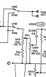
The C8 / R17 combination concerns me a bit as 8uf Dynamicaps are 1.28" (33mm) in diameter. If I use a 1uf cap, R17 at 100K brings the -3db point to 1.6Hz. All other resistors for the high pass filters throughout the preamp are 1M (R20 in the line and all phono stage). I was told that I could increase R17 (1M is the datasheet max) to perhaps ~500K or so? So, it seems my options are:
Thanks,
Chris
Still haven't changed these yet
but had a question or two regarding sizing. I've decided to go with Dynamicaps and am going to do the line stage only at this time. The heat shields on the PCB allow caps up to 18mm or so (maybe 20mm) if I retain them (which Anatek recommended I do). This means 1-2uf caps max if I stay with that.An externally hosted image should be here but it was not working when we last tested it.
The C8 / R17 combination concerns me a bit as 8uf Dynamicaps are 1.28" (33mm) in diameter. If I use a 1uf cap, R17 at 100K brings the -3db point to 1.6Hz. All other resistors for the high pass filters throughout the preamp are 1M (R20 in the line and all phono stage). I was told that I could increase R17 (1M is the datasheet max) to perhaps ~500K or so? So, it seems my options are:
- 1 Use 1uf and leave R17 alone... it will be fine at 1.6Hz
- 2 Use 8uf and leave R17 alone, you don't need the cap shields (or another value? 4uf? other?
- 3 Use 1uf and change R17 to ~500K (or another value)?
Thanks,
Chris
Just an update on this. I found the noise (hum) problem I was having, thanks to some prodding from Alan (VivaVee): the heater supply. It had ~50mV of ripple on it. After being strongly prodded, I took a look at the layout and found some sub-optimal connections. Moved them and added a cap from the LM350K datasheet. No ripple that my scope will trigger on (looks flat), and no hum.
I borrowed a pic from max29 earlier in the thread. This is an earlier board than mine (SA5, not SA5.1?)
On the left side, towards the center, there is a + and - connection. This is the heater input DC voltage from the bridge. Notice "C" and "5". These are the output to the regulator and the - output of the heater to the main board. Notice C75. This is the first filter cap for the heaters. Taking the input to the regulator and the circuit output after filtering might be a good idea
The resistor (R72) from the adjust terminal (BD) to the output (trace that "5" is on) is also tied in prior to the cap.
Thanks Alan! (and Chris)
One thing that always disturbs me is when someone fixes something in a thread like this, and never reports back what the final solution was. So, I am.
Attachments

Last edited:
Help me identifying the capacitors
Hi all this is my first post, so glad to be here.
I recently get an SA-5.1 pre for my hifi system. Previous owners had it upgraded at line stage and phono stage (standard and premium respectively) to Mike Elliott. Now I want an upgrade at power section. I don't want to send the item to US, so I want to do it here in Turkey. I'm novice about diy so have it done a technician but I need help to identify and choose replacement parts. This picture is power section inside the main chassis:
I can see:
10uf 400Vdc
110uf 100Vdc
1uf 210 Vdc
0,47uf 210Vdc
And this one is the from the power supply unit:
5v 4700 (uf ?)
16v 2200uf
I can't see a proper name on the 4 big ones. Just 500 "Vdc"
I looked in to the Percy Audio catalog but couldn't see the parts. 210Vdc value seems to be rare. So please show me the way, I need help
Hi all this is my first post, so glad to be here.
I recently get an SA-5.1 pre for my hifi system. Previous owners had it upgraded at line stage and phono stage (standard and premium respectively) to Mike Elliott. Now I want an upgrade at power section. I don't want to send the item to US, so I want to do it here in Turkey. I'm novice about diy so have it done a technician but I need help to identify and choose replacement parts. This picture is power section inside the main chassis:
An externally hosted image should be here but it was not working when we last tested it.
I can see:
10uf 400Vdc
110uf 100Vdc
1uf 210 Vdc
0,47uf 210Vdc
And this one is the from the power supply unit:
An externally hosted image should be here but it was not working when we last tested it.
5v 4700 (uf ?)
16v 2200uf
I can't see a proper name on the 4 big ones. Just 500 "Vdc"
I looked in to the Percy Audio catalog but couldn't see the parts. 210Vdc value seems to be rare. So please show me the way, I need help
Read the thread. HV reg section is in post 214. PSU itself is in post 220. My schematic, but more accurate than the official one. Any schematics you find may not be accurate, so compare to what is in there. Published schematics are likely the plain SA3/SA5 rather than the .1 versions.
Firochromis: someone has already recapped that PSU as stock they have 2 large caps (both 100uf/500V), not 4 as yours has. Yes, they need to be 500Vdc. The first cap (C77 IIRC, right one as you look at it from the front) should really be <50uf according to the tube datasheet for the rectifier. I would use something like a Panasonic TSUP if you can find them. 105ºC would be a bonus.
If you are looking for boutique, I have a 100uf/500Vdc Elna Cerafine that I used for awhile in mine (had a pair of them). I replaced one with a 47uf. Not the easiest to fit as they are big. Mine is in the FS section. Otherwise, not much available for boutique in HV these days.
EDIT: also look at this thread
http://www.diyaudio.com/forums/analog-line-level/153223-counterpoint-sa5-preamp-problem-8.html
I would pay attention to whatever Chris (anatek) or Alan (VivaVee) recommend, as they have tons of experience with these and know what they are talking about. I would listen to this regardless of what you have read ANYWHERE else.
EDIT 2: These are what I used in the HV reg section of mine: 150uf / 350v, VK Series BlackGate. Still available at partsconnexion, maybe elsewhere. You'll need 3 of them. Read post 43 in the link above re. caps.
Last edited:
Hi people,
As you know SA-5.1's has a High & Low Gain MM selector and two sets of phono inputs at the back. In my unit Low Gain input has been disconnected by Mike Elliott for reducing complexity at the signal path. Now things turned out for me to use two tonearms on my turntable and changing interconnects is not working for me. One of the arms will have a 5mV MM cartridge, other will have a LOMC connected to a Counterpoint SA-2 and then to SA-5.1.
Since both will be around 5mV input and the necessary signal path for the high & low gain input is bypassed, I believe that adding a toggle switch to the path will not harm the signal. What do you suggest for this? The original toggle switch is ok to use or a rotary switch would be better. Can you please help me?
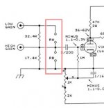
Not sure how much removing the Low Gain input "reduces complexity" as it consisted of 2 resistors (loading and 1 parallel) into the High Gain input circuitry :lol:
What toggle switch are you talking about? The High/Low gain toggle switch simply switches a high value resistor (400+K if I recall correctly) in series with the pot (low gain) or shorts it out (high gain), and has nothing to do with the phono stage; it is the line stage that it is affecting (and the phono stage, since it uses the line stage for the rest of its gain).
What toggle switch are you talking about? The High/Low gain toggle switch simply switches a high value resistor (400+K if I recall correctly) in series with the pot (low gain) or shorts it out (high gain), and has nothing to do with the phono stage; it is the line stage that it is affecting (and the phono stage, since it uses the line stage for the rest of its gain).
These SA-5 threads are excellent. I find a little BS in them, but on the whole, they offer great information that can help save the life of these units. I studied these threads before purchasing an SA-5.1 and it made my life much easier. When I do buy a preamp, I live and breath it. I study it inside and out and draw up the schematic if I can't find one. In this case, I found schematics in these threads. Thank you all. Then I look at the preamp and study it to see where it deviates from the schematic. Usually there is a good reason for a deviation, but not always. My SA-5.1 was stock (THANK GOD!). My re-build is complete and I am enjoying the preamp very much. One funny thing that I noticed that NO ONE seems to have mentioned in these threads... the original models have negative bias pots for each of the three amplification stages. The later SA-5.1 omits the pot for the first section of the phono stage. This grid for this stage is no longer provided a negative bias voltage from the negative bias supply. The grid is "grounded" just like it is in the SA-3 preamp. Here is the funny thing, if you have this factory version, take a close look at the tracing and breakout your volt/ohm meter and set it for continuity. What you will find is that the two red WIMA caps that are valued at 1uf 160v are in fact grounded at both ends and essentially not actively in the circuit! Both ends are grounded!!! They are just sitting there like spare tires on a car! I removed mine to make more room for air flow (that never hurts) and so that I can actually put them to use somewhere else. These Mike Elliott products are pretty cool, once you identify the bad flaws in the power supply and fix them.
...
What toggle switch are you talking about? The High/Low gain toggle switch simply switches a high value resistor (400+K if I recall correctly) in series with the pot (low gain) or shorts it out (high gain), and has nothing to do with the phono stage; it is the line stage that it is affecting (and the phono stage, since it uses the line stage for the rest of its gain).
Hi Chris, yes I'm talking about the High/Low gain toggle switch. My purpose here is to have a 2 channel switch for the phono input (like the 4 channel input of the line stage).
Since ME removed the low gain path, I assume that he also bypassed the toggle switch, and connected the high gain path directly to line stage. By the way I assumed the High/Low gain was located at the phono stage. Then I thought since there is an unused switch, attached to the chassis I can use it for this purpose. It saves me from the pain of drilling a hole to the front faceplate.
Regards
Attachments
By the way, I opened a Social Group here in diyaudio for users of Counterpoint. Please be a member and share the group:
diyAudio - Counterpoint Users Group
diyAudio - Counterpoint Users Group
Oh my...
Thank you Chris for clearification. So I must check if the toggle in use or not. When I switch it the sound degrades a bit both in sound level and quality.
Anyway, even if that toggle is not available my quastion is still valid. Do you think adding a switch for two phono inputs degrades the sound noticeably? What kind of switch do you recommend?
Regards,
Firat.
I did replace the gain resistors in mine with Caddock TF020 resistors in pretty much the same value as the Roedersteins that were in there. They are located up by the balance controls. This did lower the noise when in the low gain position, but I never really listened to the preamp at all after I had gotten rid of the heater noise. I can only imagine it made even more difference then.
As to what Mike did when he removed the low gain input, can you share what was done? Did he simply remove R1 (the 32.4K resistor) and the corresponding Ra loading resistor from each channel?
Because the phono is such a low level signal, implementation of the switch would need to be done carefully. First problem is how would you switch out the existing high gain input? Or would you cut the traces or wiring from the existing high gain input and rout the jacks to a switch to control which set of jacks would be used? That is probably the best route. The gain switch is the proper type (DPDT, On-On), but is a PCB mount type so would need to be disconnected. You would need to determine whether you wanted the preamp left in high or low gain and deal with the gain resistors accordingly (leave in for low gain, short out for high gain).
I might be tempted to leave it alone (possibly even restore the high gain MC section), and use an external switch box?
BTW, the stock switches in the preamp are TOCOS. Michael Percy Audio sells them, but the DPDT On-On is no longer available. I would look for a good quality switch with silver contacts if you go down this path. I would place it on the back panel, as close as possible to the phono jacks.
Last edited:
[FONT=.HelveticaNeueUI]Dear Chris, thank you for your continuing support. I appreciate that.[/FONT]
[FONT=.HelveticaNeueUI]
[/FONT]
[FONT=.HelveticaNeueUI]ME simply removed R1 and Ra but the toggle switch itself is still connected to PCB. Switching it to low gain "differs" the sound. I think it is a degradation.[/FONT]
[FONT=.HelveticaNeueUI]
[/FONT]
[FONT=.HelveticaNeueUI]Now I believe it is best to add a new rotary switch. What I have in mind is to mount a Seiden rotary switch to the very back of the side plate, closest point available to phono inputs. It will be a 2-pole&6-way switch. Phono inputs will connect to this switch and the out of this switch will connect to the appropriate place at the PCB.
Well, this is a DIY forum right, trials are welcomed. I have a second idea to add to this plan. What about buying a 4-pole&6-way switch and adding the line stage inputs to this switch also? This plan has a few benefits like
- Removing the current switch and using a better made switch for line stage,
- Removing the cheap Main-Phono toggle switch from signal path,
- Shortening the signal cables (this switch is a lot closer to line input RCAs)
I know it would be weird to use at that point but well, lets talk about it.
Regards,
Firat.
[/FONT]
[FONT=.HelveticaNeueUI]
[/FONT]
[FONT=.HelveticaNeueUI]ME simply removed R1 and Ra but the toggle switch itself is still connected to PCB. Switching it to low gain "differs" the sound. I think it is a degradation.[/FONT]
[FONT=.HelveticaNeueUI]
[/FONT]
[FONT=.HelveticaNeueUI]Now I believe it is best to add a new rotary switch. What I have in mind is to mount a Seiden rotary switch to the very back of the side plate, closest point available to phono inputs. It will be a 2-pole&6-way switch. Phono inputs will connect to this switch and the out of this switch will connect to the appropriate place at the PCB.
Well, this is a DIY forum right, trials are welcomed. I have a second idea to add to this plan. What about buying a 4-pole&6-way switch and adding the line stage inputs to this switch also? This plan has a few benefits like
- Removing the current switch and using a better made switch for line stage,
- Removing the cheap Main-Phono toggle switch from signal path,
- Shortening the signal cables (this switch is a lot closer to line input RCAs)
I know it would be weird to use at that point but well, lets talk about it.
Regards,
Firat.
[/FONT]
The difference between the high and low gain on mine was pronounced. Much louder in the high gain setting. I used mine in the low gain setting most (all?) of the time.ME simply removed R1 and Ra but the toggle switch itself is still connected to PCB. Switching it to low gain "differs" the sound. I think it is a degradation.
Why a rotary if you go this route? A simple high quality toggle switch would be perfect for this.Now I believe it is best to add a new rotary switch. What I have in mind is to mount a Seiden rotary switch to the very back of the side plate, closest point available to phono inputs. It will be a 2-pole&6-way switch. Phono inputs will connect to this switch and the out of this switch will connect to the appropriate place at the PCB.
I dunno about this choice. First off, the Tocos toggle switches used here are high quality. Granted, the Lorlin rotary switch used isn't the greatest. Finding a higher quality rotary switch isn't too difficult; implementing it well might be, given the space-restrictive physical form factor of this preamp. The input connector cabling goes to specific points on the PCB (RIAA stage H/L gain sections, and Line inputs 1-4). A rotary switch is going to switch the selected input to a single output. Not sure what you are going to do with that other than route it back to the PCB connections for the current Lorlin switch. There are input resistors on each line input, and of course the RIAA network for the phono 1 and 2.Well, this is a DIY forum right, trials are welcomed. I have a second idea to add to this plan. What about buying a 4-pole&6-way switch and adding the line stage inputs to this switch also? This plan has a few benefits like
- Removing the current switch and using a better made switch for line stage,
- Removing the cheap Main-Phono toggle switch from signal path,
- Shortening the signal cables (this switch is a lot closer to line input RCAs)
I know it would be weird to use at that point but well, lets talk about it.
Regards,
Firat.
- Home
- Amplifiers
- Tubes / Valves
- Counterpoint SA 5.1