Some question:
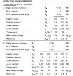
1, In the ECL82 Philips data sheet I see on the triode section operating characteristics 2 different version.
First (A) with cathode resistor (2.2K)
and second (B) without cathode resistor.
What and why is this differences? Which one is better?
2, Some people says that pentode can operate only with feedback, but some says without it the amp measures bad, but sounds better! What is the true?
Tyimo
Tyimo said:2, Some people says that pentode can operate only with feedback, but some says without it the amp measures bad, but sounds better! What is the true?
A pentode without feedback is a current amplifier. Used with an appropriate speaker it should be fine.
In a world of speakers designed for voltage amps it would be very wrong.
dave
With a fullrange speaker? No Xover.Used with an appropriate speaker it should be fine.
Tyimo
None is better !
Second option (B) is usually usable at low levels, but . . .
There are only two exemples on how you may use that tube . . . among thousands other ways.
You should first know what you are designing for: Max gain, lower noise, minimal distortion, higest output level, wider bandwith, etc ...
Wich source and wich load.
In short, best compromise ! Nobody -nothing- is perfect")
Yves.
Second option (B) is usually usable at low levels, but . . .
There are only two exemples on how you may use that tube . . . among thousands other ways.
You should first know what you are designing for: Max gain, lower noise, minimal distortion, higest output level, wider bandwith, etc ...
Wich source and wich load.
In short, best compromise ! Nobody -nothing- is perfect
Yves.
The second example is using grid leak bias (like in my design). This uses the trickle current of the grid to create a bias point. It works well and sounds good with two points to bear in mind;
1- because of the exceptionally high value of the grid resistor (1-10M) - it can be a bit hissy, as it amplifies the resistor noise. Not a major issue for me, but it might be for you.
2- It will bias up to about 1V (though the actual value is impossible to measure because the probes will effect the operating point. I wouldn't allow the input to approach that 1V, I would only run it up to about 0.5V and this way it stays nice and linear. Again this is why I have a large input signal step down.
In my design the grid leak bias is shared between the two valves of the LTP, this creates almost perfect LTP behaviour. If I put a CCS in the tail that would be even better - but no CCS's allowed in this design.
Shoog
The 10R resistor is way off - you should be thinking something like 1K.
Yes, this is why I was asking is it O.K. or not. I thought it is the second (B) option, without cathode resistor.
As I know it is also a proven design that sounds good. (?)
The partial feedback arrangement dramatically lowers output impedance which allows the outputs to bite on the low inductance.
However the original place where I found a reference to using mains toroidals as output was on Steve Benchs website, and he established that the toroidals he was using had primary inductances much higher than your figures suggest.
My experience of using toroidals as outputs has been that on my 6080 amp, with no feedback, the bass went down to 10hz without issue. This is the same on my Tabor clone. So no issues in two cases. However on this amp when I was running it as my main amp (rather than its intended headphone duty), the bass was much recessed and softer. I partly put this down to the mismatch in the transformer I was using and the speaker load of 4R. However this design used less feedback and may present issues with inductance. Unfortunately without replacing the transformers I cannot realistically say with certainty.
There is a suggestion that different toroidals may have different primary inductances - and sofar I have just been lucky with the batch I have used. On my main power amps I use models with 200VA+ ratings and I think this helps low frequency extension, but the physics of it says that the smaller the toroidal the bigger the primary inductance. I would always tend to use ones rated at least 4x expected output power.
i am very much a suck it and see person and sofar it has worked for me. I would say in conclusion that given a low enough output impedance (which I have always tried to design in) then they work very well.
Hope that helps.
Shoog
Thanks Shoog!
Could you tell me how many Henry has your primer inductance?
Tyimo
Yes, by me too.but the physics of it says that the smaller the toroidal the bigger the primary inductance.
Could you tell me how many Henry has your primer inductance?
Yes. I use 5x. like Menno van der Veen....I would always tend to use ones rated at least 4x expected output power.
Tyimo
Hi Yves!
Tyimo
Thanks! I measured with my inductance meter. Do you think the result will be different?I suggest you measure the inductance.
Quite easy: just supply the primary -with no load at sencondary- at 230 Vac and measure the current.
Tyimo
Shoog!
http://greygum.net/sbench/sbench101/
Maybe this one:
http://greygum.net/sbench/sbench/50c5.html
Tyimo
Could you tell me where can I find His text?However the original place where I found a reference to using mains toroidals as output was on Steve Benchs website, and he established that the toroidals he was using had primary inductances much higher than your figures suggest.
http://greygum.net/sbench/sbench101/
Maybe this one:
http://greygum.net/sbench/sbench/50c5.html
Tyimo
- Status
- This old topic is closed. If you want to reopen this topic, contact a moderator using the "Report Post" button.
- Home
- Amplifiers
- Tubes / Valves
- Could this become a Baby Huey killer ?