Maybe this can help. The power supply (transformer secondary+cap bank, but lets see just the cap bank) have output of (+50V)-ct-(-50V). This cap is very stiff, it always has 50V accross the 1 cap.
Say the upper transistor conducts. It will pull the +50V node (upper cap) towards ground. This is possible because the whole PS (+50,CT,-50) is floating. Say it pull 21V closer to ground.
Since the cap is stiff (always have 50V accross it), then the CT will move to (-29V) relatively to ground. 50V-21V=29V.
At this point, if you measure the (-) voltage of the bottom cap, it will sit at (-71)V relative to ground.
Since this CT is the speaker output (towards ground), then the result is (-) voltage when the upper transistor conducts. Inverting output.
Michael Chua said:
Hi Paul
Yes, PS1 will be connected to ground in a short.
No, reading will be +9V
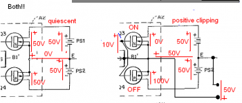
I've drawn out another diagram with Haflers' patent.
The one on the right is with Q3 injected with a 9V square wave.
E swings to + 9V rails. PS2 is now -9V to +9V, making it +18V.
But when looking at E from Ground, it would be +9V. E will have the same waveform as the injected signal.
An externally hosted image should be here but it was not working when we last tested it.
Cheers
Mike
Why did PS1 disappear in your second drawing? Q3 conducting does not short out PS1. It brings the top of PS1 to 0V, which leave the bottom of PS1 (E) at -9V relative to ground and the bottom of PS2 at -18V relative to ground.
Michael Chua said:
Our Fixed 0V is now relocated to the emitters of the transistors.
Center of PSU caps is not referenced to our Fixed 0V anymore.
Which means the "supply rails" aren't fixed at +-50V relative to ground any longer. They are now fixed at 50V above output and 50V below output. Why would they still be fixed?
When positive cycle, upper transistor conducts. Because the center point of the PSU caps is not referenced to Fixed 0V, top of upper filter cap will remain at 50V but the mid-point now will swing upwards, going positive.
How did the power supply voltage magically change? The point is that the voltage from power supply (which means measured over caps) is constant. When the N-channel transistor conducts, current will flow from "+50" to ground. The same current HAS to (Kirchoff CL) flow either through the P-channel transistor (which isn't conducting) or the load. So current will flow left to right through load which has positive resistance which makes voltage from positive output to negative output (which is the same as center tap potential) negative.
I am amazed to see you guys are not getting the floating power supply amplifer fundamental understanding.
Lumanauw and Megajocke are absolutely right. the power supply is floating but constant, its value is fixed and only the earth refernce is shifted by transistors.
DJK [master of pro amps]might contribute his valuable 2 cents as soon as he sees this thread.")
Lumanauw and Megajocke are absolutely right. the power supply is floating but constant, its value is fixed and only the earth refernce is shifted by transistors.
DJK [master of pro amps]might contribute his valuable 2 cents as soon as he sees this thread.


I made a picture (attached). Voltages in both circuits are exactly the same. _Potentials are not_ - just as expected when the ground reference is moved.
Attaching ground to different parts of a floating circuit won't change it's behaviour. (well, not true for high frequencies though - but this is just because the parasitic "components" aren't included in the schematic)
Attaching ground to different parts of a floating circuit won't change it's behaviour. (well, not true for high frequencies though - but this is just because the parasitic "components" aren't included in the schematic)
Attachments
If the ground reference is removed altogether it's obvious both circuits are exactly the same as far as this part of the circuit is concerned.
Potentials at the different nodes won't exist/are undefined though, but this doesn't matter for circuit operation.
edit: Forgot to remove "positive clipping" text. I meant "N-channel-side clipping".
Potentials at the different nodes won't exist/are undefined though, but this doesn't matter for circuit operation.
edit: Forgot to remove "positive clipping" text. I meant "N-channel-side clipping".
Attachments
I've built it once. The advantage is that it only needs to be driven by a +/-15 predrive (like opamp or discrete driver) and you can get +/-100V swing (or any voltage swing you want) from it.
You can make very clean predrive (Low voltage Jfet, classA, cascoded) since you only need +/-15V to drive the whole amp to any voltage swing you want.
It still needs proper biasing, since it is not a topology for eliminating x-over distortion. More bias, better sound.
Another advantage if the output stage is CFP (like QSC), you can direct-mounting the metal case (collector) to the heatsink without any insulator. This makes better thermal transfer.
Thanks everyone for joining in. I don't claim to be an expert on this topic so feel free to disagree.
It may be easier if we look at it like water.
Lets take a container that we can expand and contract, like one of those accordion types with pleats at the sides.
In FIG A, we place the container on a table top. If we open the valve, water flows out. Top of container drops. This is equivalent to our normal PSU where the center of 2 filter caps in series is referenced to 0V.
In FIG B, instead of placing the container on a table top, we fix the top of the container to a ceiling. When we open the valve, water flows out but bottom of container now moves upwards.
In FIG C below, we have 2 expandable containers, one attached to the ceiling and the other resting on the floor of the basement.
When we open the valve, E moves up. E will move up all the way to the ceiling when the top container is completely empty. It can't go beyond the ceiling. The bottom container will now be 2L.
Coming back to a PSU, we wonder why is it that the rail voltages are fixed when current is drawn. Looking at the containers in FIG C, its because of the "floating E". If E is fixed to 0V, rails have to drop when current is drawn. If E is floating, rails will maintain its voltage relative to 0V. Relative to E, rails have dropped.
Like Zen Mod said:
Hi Workhorse
Nice to see you chip in.
I don't see it like Crown's Grounded Bridge configuration. In this Hafler PSU, 0V is fixed. Center of PSU swings when current is drawn from the caps.
Cheers
Mike
It may be easier if we look at it like water.
Lets take a container that we can expand and contract, like one of those accordion types with pleats at the sides.
In FIG A, we place the container on a table top. If we open the valve, water flows out. Top of container drops. This is equivalent to our normal PSU where the center of 2 filter caps in series is referenced to 0V.
An externally hosted image should be here but it was not working when we last tested it.
In FIG B, instead of placing the container on a table top, we fix the top of the container to a ceiling. When we open the valve, water flows out but bottom of container now moves upwards.
In FIG C below, we have 2 expandable containers, one attached to the ceiling and the other resting on the floor of the basement.
An externally hosted image should be here but it was not working when we last tested it.
When we open the valve, E moves up. E will move up all the way to the ceiling when the top container is completely empty. It can't go beyond the ceiling. The bottom container will now be 2L.
Coming back to a PSU, we wonder why is it that the rail voltages are fixed when current is drawn. Looking at the containers in FIG C, its because of the "floating E". If E is fixed to 0V, rails have to drop when current is drawn. If E is floating, rails will maintain its voltage relative to 0V. Relative to E, rails have dropped.
Like Zen Mod said:
loudspeaker is connected between gnd and pot slider . + voltage is on upper end of pot - voltage is on lower end of pot amplifier role is to move pot slider up and down .
Originally posted by Workhorse
its value is fixed and only the earth refernce is shifted by transistors.
Hi Workhorse
Nice to see you chip in.
I don't see it like Crown's Grounded Bridge configuration. In this Hafler PSU, 0V is fixed. Center of PSU swings when current is drawn from the caps.
Cheers
Mike
we are wasting energy now ..... with trivia ......
it's exactly like this :
it's exactly like this :
Zen Mod said:loudspeaker is connected between gnd and pot slider .
+ voltage is on upper end of pot
- voltage is on lower end of pot
........
......... slider is fixed ...... but amp moves entire pot down and up
..
Zen Mod said:we are wasting energy now ..... with trivia ......
it's exactly like this :
If everyone who is still confused would just sit down, draw it out and analyze it they would realize they're making this a lot harder than it has to be.
Analogies won't help when they are wrong.
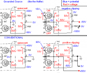
Here's what the circuit looks like. Where you put your 0V potential (ground connection) won't affect circuit operation - only node potentials.
(positive clipping as shown in the picture is for a conventional amp. With ground connected to the other output like in the Hafler, this would be full negative output of course)
Attachments

Michael Chua said:In this Hafler PSU, 0V is fixed. Center of PSU swings...
Hi Michael,
I think this quote is the heart of your misunderstanding of this circuit: The center of the PS does not swing. It's the ends of the power supplies that swing (i.e. get grounded to some extent or other through the outputs). Or, alternatively stated, its the whole PS that moves up and down, but the center point will always be at exactly the middle voltage between V+ and V-.
There will always be 126V from V+ to V- in the 9505, or 18V in your earlier example, and the middle point (OUT+) will always be halfway between the two potentials. How that middle point relates, potential-wise, to ground depends on how strongly coupled to ground V+ or V- is. If V+ and V- are being equally pulled towards ground (like when the amp is at idle), then OUT+ will be equal to ground potential. If V+ is pulled more strongly towards ground, then OUT+ will be negative relative to ground due to the negative potential sourced by the negative end of PS1. If V- is pulled more strongly to ground, then OUT+ will be positive relative to ground due to the positive potential of the + end of PS2.
Forget water. You need to draw this out with batteries and resistors (variable resistors if you like - in place of the outputs). You need to do this with batteries that do not disappear when the transistors are conducting. Then write in the voltages. The difference between absolute potential of a 9V battery must always be 9V from (-) to (+). If (+) is held to 1V, then (-) is going to be -8V. Period.
Zen is correct in his correct quote of himself.
Cheers,
Paul
To megajocke
Quote :
Those capactiors are just as much or as little in the "signal path" as the power supply capactitors in a conventional amplifier - the power circuit is identical, only the ground reference is different.
My answer :
I may be wrong, but I think you are missing the fact that common emittor and common collector are not functionning the same if you draw the Thevenin equivalent:
- In the common collector situation (emittor follower), the output impedance is low by essence and not too influenced by the resistance on the collector side (here the PSU, an imperfect voltage source, with an imperfect PSU cap) if the beta of the transistor is high enough.
- In the common emittor situation, the PSU is directly in serie with the load and this is part of the output impedance, not influenced by the beta of the transistor.
So I think the PSU cap is on the way of the signal in both cases, but its effect is different regarding to the topology.
What is you point of view on that?
Regards
I think this quote is the heart of your misunderstanding of this circuit: The center of the PS does not swing. It's the ends of the power supplies that swing (i.e. get grounded to some extent or other through the outputs). Or, alternatively stated, its the whole PS that moves up and down, but the center point will always be at exactly the middle voltage between V+ and V-.
Hi Paul
I really appreciate your explanation but I am having difficulties seeing this. If the center of the PS does not swing, how is current going to flow through the speakers? One of them have to change so that a potential difference is there for flow of current. So, if "E" doesn't move, then 0V must move. Help me out here. My learning is very slow.
Let's assume upper N-Fet shorts, what will be the voltage of the top supply rails?
An externally hosted image should be here but it was not working when we last tested it.
Cheers
Mike
If the N-Channel shorts, the top of PS1 will be clamped to 0V. However, PS1 will still be generating 63V. That means that E will be at -63V relative to ground, and the bottom of PS2 will be at -126V relative to ground.
So the speaker will feel -63V DC.
Basically, what I was saying before was that E/+OUT doesn't swing or move relative to the power supplies. It will always be right in the middle of PS1 and PS2. But, the whole stack, PS1+E+PS2 DOES move up and down based on the conduction of the output transistors.
So the speaker will feel -63V DC.
Basically, what I was saying before was that E/+OUT doesn't swing or move relative to the power supplies. It will always be right in the middle of PS1 and PS2. But, the whole stack, PS1+E+PS2 DOES move up and down based on the conduction of the output transistors.
- Status
- This old topic is closed. If you want to reopen this topic, contact a moderator using the "Report Post" button.
- Home
- Amplifiers
- Solid State
- Could someone explain this Hafler/Strickland output topology to me?