.....I'll be balancing my platter.
Absolutely. I wouldn't dream of suggesting that one not make efforts to balance the platter. I just feel more comfortable when I know what's going on. I've been tripped up too many times by faulty assumptions, so I'm constantly testing them. All this experiment proves to me is that I don't know what's going on, and that I have more to learn.
Hey pixpop,
I didn't think you had, kind sir") , my stating that I was going to balance was in conclusion to my own internal argument. I'm not at all sure it will make a noticable improvement to my table, and it will take some real effort to do it. In the end, I figured I'd rather be "safe than sorry" in this regard.
, my stating that I was going to balance was in conclusion to my own internal argument. I'm not at all sure it will make a noticable improvement to my table, and it will take some real effort to do it. In the end, I figured I'd rather be "safe than sorry" in this regard.
Can't argue with that. I have fallen into the "me too" trap more times than I care to admit.
It tripped me up at first as well, it sure seemed that the solder roll would give you "wow" in spades. Thats why I spent enough time thinking about it to come up with the "possible" answer I posted above...we all have a lot to learn.
-Casey
Absolutely. I wouldn't dream of suggesting that one not make efforts to balance the platter.
I didn't think you had, kind sir
, my stating that I was going to balance was in conclusion to my own internal argument. I'm not at all sure it will make a noticable improvement to my table, and it will take some real effort to do it. In the end, I figured I'd rather be "safe than sorry" in this regard.I just feel more comfortable when I know what's going on. I've been tripped up too many times by faulty assumptions, so I'm constantly testing them.
Can't argue with that. I have fallen into the "me too" trap more times than I care to admit.
All this experiment proves to me is that I don't know what's going on, and that I have more to learn.
It tripped me up at first as well, it sure seemed that the solder roll would give you "wow" in spades. Thats why I spent enough time thinking about it to come up with the "possible" answer I posted above...we all have a lot to learn.
-Casey
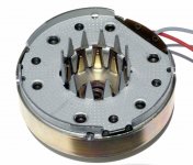
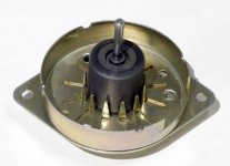
pixpop said:EC8010, can you show us the rotor as well?
At your command...
Attachments
EC8010-
Thanx for that. The only synchro motors I have seen apart are the Hursts. The designs are similar (pole shape and number) but yours has a much better build. The Hurst is only bushed at the top (the rotor magnet “hangs” from it), and the magnet is hollow. It also appears from the picture that the fit/finish is better than Hurst.
It's obvious to me now why the better Mfg.'s stay away from Hurst. I'm sure the Philips/Airpax/Premotec/McLennan is quieter, and if I had started with it, I may not have had to go to the lengths I did.
-Casey
Just to drop back for a moment to the earlier discussion of motors and their poles, I took this photograph of the inside of the Philips/Airpax/Premotec/McLennan synchronous motor used by Linn and Rega etc.
Thanx for that. The only synchro motors I have seen apart are the Hursts. The designs are similar (pole shape and number) but yours has a much better build. The Hurst is only bushed at the top (the rotor magnet “hangs” from it), and the magnet is hollow. It also appears from the picture that the fit/finish is better than Hurst.
It's obvious to me now why the better Mfg.'s stay away from Hurst. I'm sure the Philips/Airpax/Premotec/McLennan is quieter, and if I had started with it, I may not have had to go to the lengths I did.
-Casey
I browsed very briefly through this thread. I'm an industrial kind of guy, so I'm used to working with AC frequency drives and PWM control. If you can find a small enough motor (I'm sure you don't want a C face motor for this thing), You can get a small AC freq drive at a very reasonable price. It will convert 110V to 240 3 phase. Check automationdirect.com, they have one for about $100. As for control of it, I would probably use either an encoder or a whole lot of flat head screw faces with an inductive proximity switch. This would give you X pulses per revolution which you would resolve with the digital panel meter into RPM. Most panel meters can be purchased with an analog output (0-10V or 4-20mA) which can be fed to the freq drive. Now you have PWM control over your turntable speed! Just my 2 cents. I'll continue lurking now.
Casey,
You need to try some sex! Pardon ??
Back about 16 pages, you were into mat material.
Condoms are made from extraordinarily thin latex and perhaps better still, if the sex industry didnt invent it, they sure are it's foremost promoters, liquid latex.
Just a thought, even a diversion.
Like everyone else who has watched this project and those who've posted, congratulations for the work, the perseverence, the inspiration to everyone else and, have you noticed that you've also achieved a likely first:- no detractors.
Graeme
Hello Graeme...welcome to the forums,
Aren't the sheep already a little neurotic in your neck of the woods?
That is an interesting idea. The key would be to get a layer thin enough as to not de-couple the album from the platter..hmm.
The "mat" is one of the unknowns for me. I have thought about a lot of different materials (as you read), and I think I might set it up with a changable top layer (mat), about 1/8" thick, so that I can experiment with different materials/coatings.
Oh yea..I need another diversion
-Casey
You need to try some sex!
Aren't the sheep already a little neurotic in your neck of the woods?
Condoms are made from extraordinarily thin latex and perhaps better still, if the sex industry didnt invent it, they sure are it's foremost promoters, liquid latex.
That is an interesting idea. The key would be to get a layer thin enough as to not de-couple the album from the platter..hmm.
The "mat" is one of the unknowns for me. I have thought about a lot of different materials (as you read), and I think I might set it up with a changable top layer (mat), about 1/8" thick, so that I can experiment with different materials/coatings.
Just a thought, even a diversion.
Oh yea..I need another diversion
-Casey
An overdue update..
The hip has healed enough (just need a cane now) that I can work on the table in earnest again. Before I could do anything else, I needed to true up the bottom of the platter. I decided the best way to accomplish the job (since the bearing is on the wrong side for this) was to make a “puck” that fit snug, but turnable, in the hole that holds the bearing housing. I then bolted this to my mill table, and liberally slathered it, and the table, with grease...

I then laid the platter over the puck upside-down. I now had a “skid plate” that I could spin by hand. I ran my indicator, and marked the low point...

I set the end mill .005” lower than this spot, and milled the surface...

Worked like a champ. A little dust did manage to mix with the grease, which scratched the primer on top slightly..big deal.
The value of balancing the platter became obvious quickly. Even though I'm sure additional balancing is needed, the improvement this made is significant..it spins much easier/longer now.
The rest of my time I have been spending tooling up the dividing head to cut the strobe. In the process I have discovered a wee little problem with it. When I made the spindle, many moons ago, I made the worm gear integral with the spindle, that is, the whole shooting match is cut out of one piece. Somehow I managed to get the gear center off the spindle center slightly. The effect of this is that it gets tight during about 90 deg. Of the rotation. This will no doubt cause an error in the spacing..just how much is the question. I believe that as long as this error is less than .01” or so at the platter edge I can live with it. That means the error at the spindle needs to be around .001” (the error gets amplified by the diameter of the piece your cutting. Here is the head set up with the arbor beside the plates I drilled. It's resting on it's incomplete riser...

To test the error, I will wrap the platter in masking tape, and with a punch point in the mill chuck, prick the tape at each interval, and measure the distances between them. If the error is acceptable I will cut the pattern, if not, I will figure out how to replace my worm gear and come back to it later.
Man it feels good to get back to work on this
-Casey
The hip has healed enough (just need a cane now) that I can work on the table in earnest again. Before I could do anything else, I needed to true up the bottom of the platter. I decided the best way to accomplish the job (since the bearing is on the wrong side for this) was to make a “puck” that fit snug, but turnable, in the hole that holds the bearing housing. I then bolted this to my mill table, and liberally slathered it, and the table, with grease...
I then laid the platter over the puck upside-down. I now had a “skid plate” that I could spin by hand. I ran my indicator, and marked the low point...
I set the end mill .005” lower than this spot, and milled the surface...
Worked like a champ. A little dust did manage to mix with the grease, which scratched the primer on top slightly..big deal.
The value of balancing the platter became obvious quickly. Even though I'm sure additional balancing is needed, the improvement this made is significant..it spins much easier/longer now.
The rest of my time I have been spending tooling up the dividing head to cut the strobe. In the process I have discovered a wee little problem with it. When I made the spindle, many moons ago, I made the worm gear integral with the spindle, that is, the whole shooting match is cut out of one piece. Somehow I managed to get the gear center off the spindle center slightly. The effect of this is that it gets tight during about 90 deg. Of the rotation. This will no doubt cause an error in the spacing..just how much is the question. I believe that as long as this error is less than .01” or so at the platter edge I can live with it. That means the error at the spindle needs to be around .001” (the error gets amplified by the diameter of the piece your cutting. Here is the head set up with the arbor beside the plates I drilled. It's resting on it's incomplete riser...
To test the error, I will wrap the platter in masking tape, and with a punch point in the mill chuck, prick the tape at each interval, and measure the distances between them. If the error is acceptable I will cut the pattern, if not, I will figure out how to replace my worm gear and come back to it later.
Man it feels good to get back to work on this
-Casey
Well hell..I did some testing on my Div. head error, and lets just say that it's accurate enough for bolt patterns, but little else. So I visited the local dist. for all things mechanical and ordered a new gear and worm. The gear is in stock in L.A., and will be here in a few days..the matching worm wont be available for three weeks 
Looks like my strobe will have to wait a while. I'm going to follow through with making the rest of the bits I need to cut the pattern, and then move on to the motor mount..with any luck it will be spinnin' again this weekend.
-Casey
Looks like my strobe will have to wait a while. I'm going to follow through with making the rest of the bits I need to cut the pattern, and then move on to the motor mount..with any luck it will be spinnin' again this weekend.
-Casey
Hi Casey
Still pulling mechanical rabits out of conceptual hats, I see!
Brilliant job of truing up the platter.
On the topic of the strobe: how 'bout instead of all this complex stuff with the dividing head, you take a feather from the cap of our friends in the past and put the strobe on the underside edge of the platter and use a small mirror to view it (ala 1980s Pioneer, Technics, etc.). You will need a small 60hz light source down there too, but that is very minor.
I have a mid-80s Ariston that has a DC motor - their strobe is etched on the outer edge of the bottom of the platter. A little neon pea bulb gives the strobe light.
So, how to get the pattern on the bottom of your platter? Photocopy the pattern on an existing strobe-marked platter onto a sheet of clear printing film - the kind used for overhead presentations. You might also lay out the pattern on a computer and print it on the clear film.
Whichever, trim the clear film into a ring and affix it to your platter underside with clear silicon seal. The net weight should be less that 5 grams and it can be peeled off if you want to try something else.
The best part of this (untried) idea is that the clear 'overhead transparency' film is that it is extremely stable under significant temperature changes. I have used it in 11" X 17" sheets through a laser printer ( > 350degF ) for prrecise scale layered drawings used in engineering presentations. After printing and cooling a dozen sheets can be stacked together with registration marks varying less than 0.002"
Just an Idea. If you want, I can send you a photocopy of my Ariston platter - is has both 50Hz and 60Hz strobes ofr 33 & 45 rpm.
Jess
Hi Jess..I saw your post after I started this one
Your idea is a good one..in fact I started out to do more or less what you suggested, I even picked up some Lexan to make a prism out of. Ultimately I decided I wanted the strobe visible from the listening spot. Even if I put it on the bottom, I would probably cut it. Getting the pattern even a few thousandths out of center will cause the strobe to “wobble” (more so than uneven spacing), no big deal if it's a temporary pattern tossed on top to check the speed, but it would drive me nuts if permanent. Who knows? If I get tired of chasing perfection I may fall back on your plan.
Back to my post...
Ok, I need comments on my strobe plan.
I had a “duh” moment when my last strobe was spinning down at shutoff and, I noticed it syncing up at even intervals of the intended speed. This late realization got me thinking about it, and I realized how much easier it would be cutting half as many divisions..about half as hard if my math is right. This would also allow me to use the .125” endmill to cut the 33 pattern instead of the .0625” drill bit. So I've decided to go all Micro Seiki on the pattern (kinda). With .125”x.2” bars, the optical space between the strobing bars of .045” will make for a sharp line to check speed with. The only disadvantage I can see cutting 108 vs. the calculated 216 division, all things being equal, is a reduction of the effective brightness (each bar fills the pattern in twice)..am I wrong?
From an aesthetic point of view, I really didn't like the smeared white bands the pattern not under the strobe painted while it was spinning, though everybody that saw it thought the blue strobe was very cool. So I've decided to try a “ghost” strobe with clear fluorescent paint lit up with a UV led. A couple of things I need to sort yet. First where to source a UV led, the faq for this product states a wavelength peak of 365 nm is optimum. Any recommendations here would be greatly appreciated. Second, I need a good UV blocker I can coat a clear piece of plastic with. I want to block any reflected UV before it gets to the focused eyeball. Again, any and all suggestions are welcome.
-Casey
It helps to drive the LED(s) with an extreme duty cycle and lots of current. A short, very intense pulse. I built mine this way. It flashes at 120 Hz, with about a 1% duty cycle. I'm putting almost an amp through the LED. But this is a portable unit.. not part of the TT. Maybe you wouldn't want current transients like that near your cart.
I don't see any speed variations (unless I put my finger on the platter to slow it down) so I'm wondering if this is after all the best method. Given that I just threw this TT together out of salvaged parts, I expected some variation.
If the strobe pattern appears stationary, is that it? That means the speed is good enough? How meaningful is this method?
- Status
- This old topic is closed. If you want to reopen this topic, contact a moderator using the "Report Post" button.
- Home
- Source & Line
- Analogue Source
- Corian Turntable Fun