#20
what is a PAS board? Please show me the circuit you tested.
This one is very bad. I did not tell that Allen Wright is doing all wrong.
I don't know him and I don't know what he is doing.
I know a lot of solid state amps with quite impressive results.
(Bipolar and FET)
Kind regards,
Darius
Hi SY,Originally #20 posted by SY
Anyway, I grabbed a PAS board and did a few mods to simulate this circuit. ...
what is a PAS board? Please show me the circuit you tested.
Originally #20 posted by SY
Regarding cascodes, you might want to review FET operation and maybe stoop to actually doing some bench testing. Allen Wright has published his results and they are quite impressive. I'll let you explain to him why he's doing it all wrong.
This one is very bad.
I did not tell that Allen Wright is doing all wrong.I don't know him and I don't know what he is doing.
I know a lot of solid state amps with quite impressive results.
(Bipolar and FET)
Kind regards,
Darius
The PAS is probably the best-selling tube preamp of all time. Dynaco sold that series for maybe 20 years. An entire generation of diyers cut their teeth on these and there were probably more analyses and modifications published about them than for any other tube preamp ever made. Anyone of my vintage will have a few in the junkpile; I probably have 4 or 5. You should have zero trouble finding a schematic.
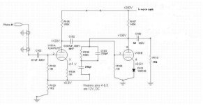
The Copland removes Dynaco's 10k grid stopper (which compromises noise), removes the positive feedback used by Dynaco to pump the marginal open-loop gain, and seeks to recover the lost gain by subbing a diode for the cathode resistor of the second stage. This version also decreases the feedback at low frequencies to try to make up for the lower open-loop gain. Plate resistors and first stage cathode resistor are identical as are supply voltages. The sacrifice here is overload performance, and the 10kHz waveform was badly distorted at 10mV in. Going even slightly beyond that induced gross blocking. This made the capacitance measurement a little challenging!
When I have time later today, I'll mark up the Copland schematic to indicate the exact test circuit. It does not differ significantly (for the purposes of input capacitance measurement) from the Copland. And I'll verify the input C using a separate measurement method. But again, this is something I know well, having had to try to match finicky MMs to various modified PAS preamps over the years.
Type "dynaco pas" into your favorite search engine. This is the first entry (out of 9,000 or so):
http://www.curcioaudio.com/dynadr_3.htm
Sheldon
http://www.curcioaudio.com/dynadr_3.htm
Sheldon
Allen Wright is a rather well respected designer and manufacturer of tube audio gear. He is also rather well known for a major series of mods targeted at Sony SACD players like the SCD-1, SCD-777ES, etc. Link to his site here: http://www.vacuumstate.com/ Only a relative newbie would be totally unaware of his existence as he has been in the business for as long as I can remember which is at least 18 or more years.
Seems like getting your (our) points across might be tougher than flogging a dead horse. I've pretty much given up at this point..

Yippy ti yi yo get along little electrons it's your misfortune and none of my own
Yippy ti yi yo get along little electrons you know that the lowly 12AX7A will be your new home
Sorry I couldn't resist, and my apologies to Chris Ledoux for perverting his song..
Seems like getting your (our) points across might be tougher than flogging a dead horse. I've pretty much given up at this point..
Yippy ti yi yo get along little electrons it's your misfortune and none of my own
Yippy ti yi yo get along little electrons you know that the lowly 12AX7A will be your new home
Sorry I couldn't resist, and my apologies to Chris Ledoux for perverting his song..
Originally #20 posted by SY
...
Using a 10kHz excitation and a Leader LCR740 cap bridge, I measured Cin at 112pF, pretty close to the expected value. I didn't measure 10kHz distortion this time, but from having done it with similar circuits a few dozen times before, I can say with confidence that it ain't pretty, and contrary to the simple and wrong feedback model, the distortion rises with frequency.
...
I am sorry, I don't know your popes gurus etc. and I don't know all product numbers
and names. Technical things like good schematics and inside vies are more interesting
than high gloss advertising.
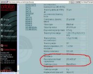
Where are the technicians here? Is nobody able to tell SY that this instrument
is not intended to measure the input capacitance of a RIAA preamp?
This is really embarrassing.
You can download the schematic and technical data of the LCR740 here:
http://bama.edebris.com/manuals/leader/lcr740/
Kind regards,
Darius
Darius,
So if you are such an expert instead of criticizing every suggestion made or experiment done by anyone here why don't you please teach us how to do it correctly??
I think SY and any number of other scientifically well grounded people have tried very hard to back up their contentions with good science.
Start by providing us with a planned experiment, a list of equipment required, and a proper scientific methodology. Explain the limitations inherent in the experiment, and the equipment used, (inherent accuracy, error contributors, etc.) explain how to overcome the limitations imposed by the test equipment, and the methodology you will use to make and interpret the measurements.
I am assuming of course that you have a very well equipped electronic workshop from which to draw the basis of your conclusions.
You raise objections, you criticize, and you contradict. You provide very little illumination (none really) of how to do these things in a scientifically correct and objective manner.
It really seems like you have some sort of axe to grind and a compelling need to prove that you are a whole lot smarter than anyone else around here. And you might well be - now go off and prove it!
We all welcome the opportunity to learn. I for one want to see concrete evidence provided by your own experiments (and not the regurgitated writings of others, instrument specification sheets and the like) for your contentions as they strongly contradict the hard won experience of many here.
Edit:
Boris I think I probably agree..
Let's see...
oldeurope said:
<snip>
Where are the technicians here? Is nobody able to tell SY that this instrument
is not intended to measure the input capacitance of a RIAA preamp?
This is really embarrassing.
You can download the schematic and technical data of the LCR740 here:
http://bama.edebris.com/manuals/leader/lcr740/
Kind regards,
Darius
Well then tell us what is!!
Darius, I wanna know an alternative way to measure input impedance including the imaginary (reactive) component of that input impedance. No hints anyone.
oldeurope said:I am sorry, I don't know your popes gurus etc. and I don't know all product numbers
and names.
Allen Wright is neither a pope nor a guru, but a designer that shares his designs with the DIY community. And you were given the citation relevant to this thread in post 10, which describes some of his design rational for the cited phono stage. You've made it clear that you like your stage better, and that you don't like a cascode input stage. I found some interesting things on your site and I learned more about plate curves for the cascode. But why the attitude? And don't play the passive/aggressive game of "who me"? The quote footnoting your posts is telling.
BTW, my favorite quote from a Texan was given by Bum Phillips. He was a well known American football coach, and known for his folksy manner. A few years after he retired from coaching, he was asked by a sports writer; "what are you doing now, Bum"? His reply: "nuthin, and I don't start doing THAT til noon".
Ot
@Sheldon,
Stop putting words into my mouth. It is bad enough that our moderator does. See #22.
And this is not for the first time!
Why this attitude?
I think, SY and his friends are talking everything bad they don't understand,
(or for any other reasons ?!) See #2
Read this one and you'll understand why I hate SY. link
There is nothing I can do because my stage has plenty novelties and is very difficult to
understand.BTW
@Boris_The_Blade,
I think, SY and his friends are running of topic, technical discussions are impossible.
I experienced this several times already.
@kevinkr
why?
Darius
Originally #33 posted by Sheldon
Allen Wright is neither a pope nor a guru, but a designer that shares his designs with the DIY community. And you were given the citation relevant to this thread in post 10, which describes some of his design rational for the cited phono stage. You've made it clear that you like your stage better, and that you don't like a cascode input stage. I found some interesting things on your site and I learned more about plate curves for the cascode. But why the attitude? And don't play the passive/aggressive game of "who me"? The quote footnoting your posts is telling.
BTW, my favorite quote from a Texan was given by Bum Phillips. He was a well known American football coach, and known for his folksy manner. A few years after he retired from coaching, he was asked by a sports writer; "what are you doing now, Bum"? His reply: "nuthin, and I don't start doing THAT til noon".
@Sheldon,
Stop putting words into my mouth. It is bad enough that our moderator does. See #22.
And this is not for the first time!
Why this attitude?
I think, SY and his friends are talking everything bad they don't understand,
(or for any other reasons ?!) See #2
Read this one and you'll understand why I hate SY. link
There is nothing I can do because my stage has plenty novelties and is very difficult to
understand.BTW
@Boris_The_Blade,
I think, SY and his friends are running of topic, technical discussions are impossible.
I experienced this several times already.
@kevinkr
why?
Darius
#32
The input capacitance is difficult to measure.
It depends in the gain of the first stage V101A
measure or calculate the gain of this triode.
The gain multiplied by the grid to anode capacitance
Cga gives you the input capacitance e.g. 31 x 1p6F = 50pF
Please note Cga is 1p6F. A bad design and stray capacitances increases it,
thus you'll get more input capacitance.
The calculated gain RIAA disconnected is lvul ≈ 30 for first stage.
With RIAA feedback it'll be decreased the higher the input frequency.
Hope it helps...
BTW: How much input capacitance is necessary? Have a look at the data sheet
of your MM pick up.
Kind regards,
Darius
Read this one and you'll understand why I hate SY.
You and my ex-wife.
Re: Ot
If you mean the "who me" wisecrack, I apologize. It wasn't necessary.
I'm mystified by all the vitriol. I didn't see anything in the link you cited that should cause "hate" to boil up - a little irritation maybe, but jeez. And the BTW link has me stumped, but I'm not interested in the explanation.
Reminds me of another quotation relating to academic infighting. Paraphrasing:
"the arguments are so vicious, because there is so little at stake"
Sheldon
.
oldeurope said:
@Sheldon,
Stop putting words into my mouth.
If you mean the "who me" wisecrack, I apologize. It wasn't necessary.
I'm mystified by all the vitriol. I didn't see anything in the link you cited that should cause "hate" to boil up - a little irritation maybe, but jeez. And the BTW link has me stumped, but I'm not interested in the explanation.
Reminds me of another quotation relating to academic infighting. Paraphrasing:
"the arguments are so vicious, because there is so little at stake"
Sheldon
.
Re: #32
Darius,
Why is it difficult to measure? You do explain what influences the capacitance, but that's not relevant for *measuring* it, or is it?
Jan Didden
oldeurope said:The input capacitance is difficult to measure.
It depends in the gain of the first stage V101A
measure or calculate the gain of this triode.
The gain multiplied by the grid to anode capacitance
Cga gives you the input capacitance e.g. 31 x 1p6F = 50pF
Please note Cga is 1p6F. A bad design and stray capacitances increases it,
thus you'll get more input capacitance.
The calculated gain RIAA disconnected is lvul ≈ 30 for first stage.
With RIAA feedback it'll be decreased the higher the input frequency.
Hope it helps...
BTW: How much input capacitance is necessary? Have a look at the data sheet
of your MM pick up.
Kind regards,
Darius
Darius,
Why is it difficult to measure? You do explain what influences the capacitance, but that's not relevant for *measuring* it, or is it?
Jan Didden
Re: #32
As long as the power supply to the phono stage is on (for gain to be had and Miller to take effect), which I'm sure SY had, the input capacitance measured at 10KHz with the LCR meter will be what the phono cart sees at 10KHz. It doesn't get much simpler than that.
oldeurope said:The input capacitance is difficult to measure.
It depends in the gain of the first stage V101A
measure or calculate the gain of this triode.
The gain multiplied by the grid to anode capacitance
Cga gives you the input capacitance e.g. 31 x 1p6F = 50pF
Please note Cga is 1p6F. A bad design and stray capacitances increases it,
thus you'll get more input capacitance.
The calculated gain RIAA disconnected is lvul ≈ 30 for first stage.
With RIAA feedback it'll be decreased the higher the input frequency.
As long as the power supply to the phono stage is on (for gain to be had and Miller to take effect), which I'm sure SY had, the input capacitance measured at 10KHz with the LCR meter will be what the phono cart sees at 10KHz. It doesn't get much simpler than that.
#38 #39
Good evening,
The input capacitance is difficult to measure directly because you must ensure
that the RIAA preamp is not over driven by the output signal level of the
instrument. You should have something like < 6mVpp @10KHz.
Verify this with an oscilloscope. Make this measurement at power off
and power on. Con -Coff is that what comes from the input stage.
Be careful not to catch external noise.
Anyone able to show me many MMs that will not be happy with say 200pF?
I think you have to add a capacitor (≈100pF) at the input of the Copland topology.
Kind regards,
Darius
Good evening,
The input capacitance is difficult to measure directly because you must ensure
that the RIAA preamp is not over driven by the output signal level of the
instrument. You should have something like < 6mVpp @10KHz.
Verify this with an oscilloscope. Make this measurement at power off
and power on. Con -Coff is that what comes from the input stage.
Be careful not to catch external noise.
Originally #2 posted by SY
Gut and rebuild. Designer parts are nice, but the basic stage is very problematic, having the same issues as the late and unlamented Dynaco PAS.
1. Input capacitance is high. Many MMs will not be happy, and any sort of MC stepup will suffer.
...
RIAA stages are very difficult to design properly, which is why there are so few good commercial designs. This is not one of them.
Anyone able to show me many MMs that will not be happy with say 200pF?
I think you have to add a capacitor (≈100pF) at the input of the Copland topology.
Kind regards,
Darius
Attachments
- Status
- This old topic is closed. If you want to reopen this topic, contact a moderator using the "Report Post" button.
- Home
- Amplifiers
- Tubes / Valves
- Copland CTA-402 Phono Section Comments