EnvisionAudio said:
What you call inoffensive is what many see pedantic. Personality disorders aside, the points Eva brought up regarding the use of a "potted block" for a floating gate-drive supply are not only relevant but exceptionally forward-thinking. I can't think of a reasonably well designed $10AUD "brick" from any supplier. Either you're making it up or you don't understand. I leave this case alone now.
What the?
1) I specifically said that the concerns raised were valid – just not the extent to which they were cited as insurmountable problems; pointing this out isn’t pedantic.
2) Small ~$10AUD single output brick converters perfectly suitable for the application are readily available (mine [xppower brand] have an isolation capacitance of 60pF) and I haven’t had any dv/dt related failures/operational or EMI issues with a bit of supply input filtering.
Thanks.
I can confirm that the prototype plays full-volume full-range music bridged into 8 ohms without heatsink. Interestingly, the power supply MOSFETs are the ones getting hotter, but still below 50ºC or so, then comes the diodes and then the class D MOSFETs. Internal rails sag to +/-27V during bass transients (using a battery as a power supply).
Eva said:I can confirm that the prototype plays full-volume full-range music bridged into 8 ohms without heatsink. Interestingly, the power supply MOSFETs are the ones getting hotter, but still below 50ºC or so, then comes the diodes and then the class D MOSFETs. Internal rails sag to +/-27V during bass transients (using a battery as a power supply).
Evita, you always speak of failures caused by Hi dv/dt rate and huge RF emissions with floating gate driver supply transformer, but i haven't seen any of its ill effects in QSC PL380, Powersoft K20KW amp......Then how is this possible!!!
Also your Gate charge of your Mosfets is 41nC only and the amp is not of KW power level driving low impedances.
In my case Qg is 250nC, 22dBu overdrive is in happening........
thats why simple bootstraping isnot going to do any wonder....
Attachments
ionutgaga said:@Workhorse:
The SFbuffer that you propose is from Ecler amp? In your opinion it is better from small smps? What curent in zenner diode? ...
No its not from ecler, its like Ecler...
")
Zener current drain is around 5mA
This scheme guarantee 0-100% dutycycle without other complexities
Workhorse said:
Evita, you always speak of failures caused by Hi dv/dt rate and huge RF emissions with floating gate driver supply transformer, but i haven't seen any of its ill effects in QSC PL380, Powersoft K20KW amp......Then how is this possible!!!
Also your Gate charge of your Mosfets is 41nC only and the amp is not of KW power level driving low impedances.
In my case Qg is 250nC, 22dBu overdrive is in happening........
thats why simple bootstraping isnot going to do any wonder....
Floating is an illusion that we create...
Transformers only provide low frequency isolation, at RF they act as resonators.Regarding these amplifiers, don't you think that here in electronics most of the time we are inventing the perfect solution for the wrong problem?
Your circuit should behave really funny when you force the parasitistic capacitances of the IRF840 to slew at over 10V/ns. If you do the math, you get 1A flowing when you charge 100pF at 10V/ns, and this is not accounting for the effect of reverse transfer capacitance on Vgs during falling edges. Now bias it with 5mA (and fool yourself thinking that only 5mA are flowing all the time).
How much voltage and current are you switching with 250nC Qg? In one of my next projects I'm going to switch up to 180V and 60A at .010 ohm typ. with 140nC typ. You may consider newer generation MOSFETs if you are switching less with more Qg... I swear that I will get it right without any "floating transformer".
If your amplifier has to accept +/-14V input (28Vpp) without self destroying (or frying the speakers, which is what happens in practice), consider a good VCA or LDR limiter stage at the input. Every good PA amplifier has one (the opposite is also true
). Consider limiting long term clipping to 30% (allowing signal peaks 3dB above maximum output).G.Kleinschmidt said:
Probably not economical for a mass-produced design, but for a one off DIY project a little $10 PCB mount DC-DC converter is the way to go.
I have already designed this DC/DC converter.
http://www.diyaudio.com/forums/showthread.php?s=&threadid=107104
But I agree from theory to Eva's statements and I do not enjoy technical solutions, which combine fundamental disadvantages with high component count.
So in the moment I am thinking more about simple low loss LC-charge pumps for all non floating auxiliary supplies and bootstrapping for the floating supply....
Eva said:
For this 100V circuit I have used 1N4148 without trouble. There is a low side diode too that ensures matched drive voltages and switching times. I think that anything storing little reverse recovery charge is OK.
Of course 1N4148 is nice, but above 70V you are living on good luck. Don't do this in your final design that you might sell. Saving zero-point-nothing cents for a proper rated diode is the most unneccessary way to get field returns.
But I definitely like your proposal to recharge the floating supply at heavy clipping.
Regarding 78xx or not: Have a look to the drift of your supplies over the automotive temp range and check the related error in dead time adjustment. I guess it will drift more than 100% of your nominal dead time. ...on the other hand: ...who cares, as long as it does not smoke?... It is up you to decide how much perfection you need.
Hi Choco
The 1N4148 from Philips that I use are rated at 100V.
I think that the local 7812 in the high side is not a good idea because 78xx regulators draw a substantial idle current, 3 or 4mA typ. according to my measurements. A micropower regulator may overcome this.
Concerning dead time, in practice IR2010 causes it to increase with temperature so no problem there. Also, the non linear nature of MOSFET drain-source capacitance comes very handy because Cds is very high when Vds is near zero, it's high enough to hold Vds down for a few ns after gate turn off and allow for small delay errors without introducing substantial dead time. Very short dead times are possible without any actual overlapping or cross-conduction.
Eva said:
Floating is an illusion that we create...
How much voltage and current are you switching with 250nC Qg? In one of my next projects I'm going to switch up to 180V and 60A at .010 ohm typ. with 140nC typ. You may consider newer generation MOSFETs if you are switching less with more Qg... I swear that I will get it right without any "floating transformer".
If floating is really an illiusion then the floating bridge is also a RF generator according to me as in Fredos amp....
Switching frequency is 250Khz, Rails are +/-180VDC
and load is 2 ohms music signal......
RDS is 0.08OHMS
ChocoHolic said:
I have already designed this DC/DC converter.
http://www.diyaudio.com/forums/showthread.php?s=&threadid=107104
But I agree from theory to Eva's statements and I do not enjoy technical solutions, which combine fundamental disadvantages with high component count.
So in the moment I am thinking more about simple low loss LC-charge pumps for all non floating auxiliary supplies and bootstrapping for the floating supply....
Hmmm. I guess that designing in a SIP DC-DC converter "black box" for the high side switch driver supply is a bit less technically adventurous than designing your own converter.
From a component/complexity POV, this was the simplest and most reliable way to provide the high side switch supply, which bounces between 0V and ~1000V in my design, so that’s what I used.
I admit that 1000V class D isn’t typical of most class D applications, but considering the fact that it worked rather well, I don’t see why the approach couldn’t be utilised in a more typical design.
The converters are readily available from stockists such as RS & Farnell, so I’ll be playing more with these in drive circuits in the future.
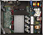
http://www.diyaudio.com/forums/attachment.php?s=&postid=1181049&stamp=1176329952
From a well know big brand… +VCC is about 200V regulated.
And please, forget the clip stuff; it is not admissible in a well designed amplifier.
As Eva said above, one must have some kind of soft-clip and/or anti-clip circuit.
From a well know big brand… +VCC is about 200V regulated.
And please, forget the clip stuff; it is not admissible in a well designed amplifier.
As Eva said above, one must have some kind of soft-clip and/or anti-clip circuit.
http://www.crownaudio.com/pdf/legacy/CE4000Schematics.pdf
Same guys… but floating (page 7) and no direct over-current detection…
Input signal limiter on page 1,18,19…
PFC Smps page 16,25
Same guys… but floating (page 7) and no direct over-current detection…
Input signal limiter on page 1,18,19…
PFC Smps page 16,25
http://www.crownaudio.com/pdf/legacy/k-series_servicemanual-schematics.zip
Same guys again… floating and no direct over-current detection…again..
Hei…!!! Floating supply is from AC line ???....
Same guys again… floating and no direct over-current detection…again..
Hei…!!! Floating supply is from AC line ???....
Nice to see that Crown is still using their BCA topology
..and they do not switch with unsaint speed, which is making parasitic inductances and capacitances less critical... Their solution is a clear statement that giant di/dt and dv/dt tend to cause evil...
Floating or not: From the schematic we cannot see how loose this floating really is. The parasitic effects of the transformers and PCB are not visible in the schematic...
But obviously it is possible to work with active floating supplies.
Regarding the adventure of designing a flyback:
IMHO small flybacks are easy to handle and quite forgiving systems. Not much adventure. Just few points to consider:
- If offline, then you have to take care for proper isolation, which is bad for the leakage inductance & efficiency. No issue at low power.
- Transformer design for good cross regulation of all outputs is contradictive to low capacitive couplings. Depending on the requirements this might hurt.
I saw no floating supplies in the schematic from post#134, they use conventional bootstrap for the high side. I have not had yet time to take a look at the contents of the zip file from post#135...
I'm busy because I have found an interesting bug in the amplifier. Tonight I was looking at the ripple on the supply rails with oscilloscope during crazy loud playback, just for fun, and I discovered traces of single random cross-conduction pulses from time to time.
Using dual trace mode to find what was being switched when the cross-conduction spikes appeared, I tracked the problem to the right channel, the inner one. This channel seems to be producing false narrow pulses at the output of the comparator during very loud playback (amp. bridged on 8 ohm speaker, 120Vpp output including some clipping). These narrow pulses result in ocasional brief cross-conduction because the IR2010 can't toggle that fast.
The problem seems to be related to crosstalk with the push-pull power supply because I saw periodic 54Khz pulses at the output of the comparator in one of the waveform captures that I did. This wouldn't come as a surprise because the push-pull PSU is dealing with 40A peaks during bass transients and toroid leakage inductance is damn evil (I have up to 50V turn-off peaks in the primary side). In fact, one of my first findings during initial testing was that the toroid produced far more EMI than the class D channels themselves...
Fortunately the other channel is clean. This is going to be a fun quiz to solve I have yet to find what PCB traces are picking up the EMI, but since the toroid is currently elevated 15mm above the PCB (for testing purposes), the first obvious fix to improve leakage inductance is to cut the excess magnet wire and solder it close to the PCB and the ground plane. The second fix would be to add a flux band to the toroid... On the other hand, the "minimalistic" push-pull PSU layout is working very well because I couldn't measure any voltage drop spikes across the GND and +12V planes while switching 40A, and PCB voltage drop was very small (in the 100mV range, due to the huge current rather than inductance).
I'm busy because I have found an interesting bug in the amplifier. Tonight I was looking at the ripple on the supply rails with oscilloscope during crazy loud playback, just for fun, and I discovered traces of single random cross-conduction pulses from time to time.
Using dual trace mode to find what was being switched when the cross-conduction spikes appeared, I tracked the problem to the right channel, the inner one. This channel seems to be producing false narrow pulses at the output of the comparator during very loud playback (amp. bridged on 8 ohm speaker, 120Vpp output including some clipping). These narrow pulses result in ocasional brief cross-conduction because the IR2010 can't toggle that fast.
The problem seems to be related to crosstalk with the push-pull power supply because I saw periodic 54Khz pulses at the output of the comparator in one of the waveform captures that I did. This wouldn't come as a surprise because the push-pull PSU is dealing with 40A peaks during bass transients and toroid leakage inductance is damn evil (I have up to 50V turn-off peaks in the primary side). In fact, one of my first findings during initial testing was that the toroid produced far more EMI than the class D channels themselves...
Fortunately the other channel is clean. This is going to be a fun quiz to solve
I have yet to find what PCB traces are picking up the EMI, but since the toroid is currently elevated 15mm above the PCB (for testing purposes), the first obvious fix to improve leakage inductance is to cut the excess magnet wire and solder it close to the PCB and the ground plane. The second fix would be to add a flux band to the toroid... On the other hand, the "minimalistic" push-pull PSU layout is working very well because I couldn't measure any voltage drop spikes across the GND and +12V planes while switching 40A, and PCB voltage drop was very small (in the 100mV range, due to the huge current rather than inductance).Eva said:I saw no floating supplies in the schematic from post#134, they use conventional bootstrap for the high side. I have not had yet time to take a look at the contents of the zip file from post#135...
???
On page 7 they do it with T101 for the for floating supply of VP CH1 +12.
The same again some pages later with T201 for the second chanel.
Well, if you make just one output per transformer then you can keep the capacitive coupling low. I think the Crown approach is not bad. But also not really cheap.
The entire design is looking like : 'Costs don't matter.'
Does anybody know to which adress I should send my application? Of course I noticed the LC-charge pump. It is similar to what I am planning since my posting #128.
But I still plan the bootstrap for upper driver as traditional simple bootstrap. I do not see problems in that..
Only my +/-15V and lower driver will have LC resonant pumps, because there the giant voltage sloping of the halfbridge has to be brought down to low voltages and I want to keep the capacitive load small.
Variations of such supplies are widely used, but unfortunately often patented. For professional applications you have to be careful.... patent check first, or hope for good luck...
P.S:
In the mean time my hard switching topic is coming nice... Thanks again for the hint with the RCL snubbering. The new set up with RCL snubber shows nearly no resonance anymore. And the almost invisible rests have a frequency around 120MHz. Means even the fundamental is nicely above UKW RF-broadcasting.
But still nobody can tell me anything about dv/dt limitations of the IRFB4321...
- Status
- This old topic is closed. If you want to reopen this topic, contact a moderator using the "Report Post" button.
- Home
- Amplifiers
- Class D
- Cool and small 2x150W class D full-range car amplifier