I recently rebuilt / restored an old Gates "Dynamote" 2-channel mixer. They're really wonderful-sounding units but a tad noisy. I had hoped to convert this one to a quieter DC filament supply but I'm not sure that's possible with the current setup.
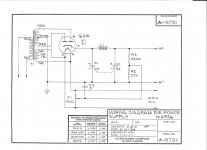
It's my dim understanding that to implement a regulated DC supply, you want the transformer to supply at least 3 "extra" volts to account for losses in rectification, filtering, and regulation. Right now the supply is at 6.6VAC, which is actually pretty good considering the transformer was designed to run on 115V.
Anyway, short of adding a dedicated filament transformer, is there any way to get there from here?
Many thanks in advance!
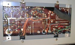
Attachments
Hm, I hadn't actually thought to characterize it other than "tube noise."
By that I mean more hi-freq stuff than AC ripple. All the caps--filtering and coupling--are new. As you know, these units have REALLY high gain and compared with modern preamps, the noise floor is just a bit high. That's why I thought that a DC supply would be a useful mod....
By that I mean more hi-freq stuff than AC ripple. All the caps--filtering and coupling--are new. As you know, these units have REALLY high gain and compared with modern preamps, the noise floor is just a bit high. That's why I thought that a DC supply would be a useful mod....
A DC supply will not improve the noise figure.
These mixers were designed for remote broadcasting 50 years ago.
Back then, noise wasn't that important. They were generally connected to equalized telephone lines.
You may be able to reduce the gain on the output stage and run the channel and master level controls higher.
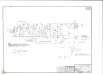
Can you post the schematic for the program output amplifier?
These mixers were designed for remote broadcasting 50 years ago.
Back then, noise wasn't that important. They were generally connected to equalized telephone lines.
You may be able to reduce the gain on the output stage and run the channel and master level controls higher.
Can you post the schematic for the program output amplifier?
I agree that you need to understand what type of noise is of concern and where it may be being generated.
Noise from some resistor types may be an issue for olde amplifiers.
The impedance of C3 in the humdinger DC elevation may be relatively high, and not bypass heater coupled AC hum currents adequately. Similarly, some more hum reduction may come from increasing C3 in the first amp stage.
Grounding scheme and wiring dress may not have been optimum.
Capacitors were relatively costly and scarce back then - C2 could be significantly increased is size to pull B+ ripple voltage down.
Some techniques for localising noise are using a spectrum analyser of output waveform, along with an AC voltage meter with good low voltage resolution and mains earth loop rejection; battery powering the input valve heater; grounding the grid directly to cathode at the valve base of the first few amp stages.
Hm, I hadn't actually thought to characterize it other than "tube noise."
By that I mean more hi-freq stuff than AC ripple. All the caps--filtering and coupling--are new. As you know, these units have REALLY high gain and compared with modern preamps, the noise floor is just a bit high. That's why I thought that a DC supply would be a useful mod....
No. The DC supply will not help the noise floor unless the problem is low frequency hum. You can prove this by using a 6V battery on the heaters and noting if the noise changes. Only if the 6V battery solves the problem, then go for DC heaters
Looking at the schematic I'd expect a lot of "tube noise" that is just the nature of pentode preamp tubes and this amp has it's share of those for sure.
Last edited:
With three high gain pentodes in cascade I'm not surprised that you have noise. You might try the old trick that Hewlett-Packard and Boonton Electronics used in their old tube millivolt meters of starving the input tube 6V filaments by running them at 5 or even 4½ volts to reduce noise. They would also use selected low noise types like Telefunkens. But that's an expensive option in todays NOS tube market.
The impedance of C3 in the humdinger DC elevation may be relatively high, and not bypass heater coupled AC hum currents adequately. Similarly, some more hum reduction may come from increasing C3 in the first amp stage.
Interesting, interesting...I'm learning a lot here. I'm not sure I quite understand the comment about C3 in the heater circuit. Can you explain the bit about "not bypass heater coupled AC hum?
As for increasing the value of the OTHER C3, the cathode bypass cap on the first tube, would that also increase gain and bass response?
I'll try the 6V battery test, that's such a simple and obvious strategy....
Thanks much!
Hum voltage couples to the grid via stray capacitance - this mechanism is minimised by the humdinger pot, which effectively couples equal and opposite signals to the grid, such that they null.
Hum voltage also completes a current loop via the resistance between heater and cathode, the cathode bias circuit, and the heater/humdinger back to ground. Increasing the heater cathode resistance (by DC elevation) will lower the hum current flowing in this loop. Lowering the impedance of the cathode bias circuit (C3 in amp circuit) will lower the hum voltage developed across the cathode bias circuit. Lowering the impedance of the humdinger wiper to ground (C3 in power supply) bypasses any HT related hum voltage, which would otherwise add itself into the loop.
Hum voltage completes that same loop via capacitance between heater and cathode - and the same comments as before are valid, except that the heater-cathode capacitance doesn't change with DC elevation. It seems that capacitive impedance is much lower than conduction related resistance for the heater-cathode interface.
Yes cathode bypass C3 will change the bass response and increase gain (compared with not having a bypass capacitor), but one of the main advantages of capacitor bypassing the cathode resistance in the first preamp stage is actually the reduction in hum provided.
Maybe best to first check if hum is a problem before chaging values without any need - eg. DC power the first stage heater (or all heaters), using a battery - I have a 7.2Ah 6V VRLA I keep just for that purpose.
Any larger value in cap is going to be better - so likely to depend what you have lying around, and what physical size suits. If you do have a hum problem, then changing those caps may still not appease the issue, as there are still other mechanisms, such as lead dress and general grounding to consider.
Ciao, Tim
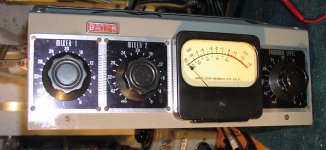
That's a Gates Bi-mote.
Unfortunately, I'm not sure that you can reduce the noise that much.
This is just from memory but, as I recall, the two inputs go directly to the Daven Attenuators. The outputs from the attenuators go to the input transformer.
About the best that you can do is to operate the mixer with the input attenuators as high as possible and the Master as low as possible.
I've always wanted to get my hands on one of those mixers and re-design it for better performance.
Nonetheless, they were good mixers for their time.
I just rebuilt one of these that had been hacked up before I got it. I removed the two-channel passive mixer section (both attenuators) and made it into what it really is; that is, a single-channel mic preamp. While mine is not dead quiet at high gain (this thing has a LOT of gain), it's certainly quiet enough to use with ribbon mics at the gain level they need. I routinely use it to mic strings from about 6-8' away and the noise floor isn't troublesome at all. I've been toying with making one of the gain sections switchable, but since it works well now I'm not that motivated to do so. I also added a switchable 20dB pad on the input so I can get the circuit gain up a bit higher for ribbon mics and pad it down for hotter mics and sources. I really like the sound of this pre, especially with ribbon mics.
Cheers,
--
Don
Cheers,
--
Don
- Status
- This old topic is closed. If you want to reopen this topic, contact a moderator using the "Report Post" button.
- Home
- Live Sound
- Instruments and Amps
- Convert Gates pre-amp to DC filament?