Hi!
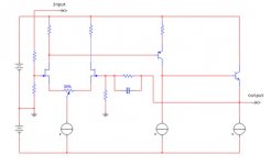
I have this circuit in my new project. I’s plays nice but I need some ideas to keep the dc offset at 0V. The problem is biggest when I start it up, DC power on and then the dc offset is about -2V. After a wile when the circuit is warm then it’s down to 0,2V.
Please give me some god ideas.
See picture...
Ola A.
Attachments
I assume you have built it.Progg70 said:I’s plays nice
The problem is biggest when I start it up, DC power on and then the dc offset is about -2V.
Have you tried shorting the input to see what effect this has on cold and hot offset?
What components and values have you used?
For differential input amps without a servo the feedback input is often:
1) tied into a variable resistor between +V and -V to sum in a warm-mode output null-offset voltage. This compensates for the imperfect matching between components
2) a large cap is placed in series with the feeback resistor to ground... typically 470uF paralled with 100pF for high freq rejection. this allows only AC feedback
Take a look at the Krell KSA100 or SysSym amp threads for examples.
you can see if you have set the amp up for zero DC output offset when fed from a low impedance source. That should be your first priority. then try refining it for warm up characteristics.Progg70 said:What result can I see if I do that?
Hi
If you add all the current sources to your per amp then your circuit is not all that different from the one that I normally use.
The main difference is that I use LM394, a dual transistor, for the input diffrential pair.
I agree with the replies you have received to date. However I have been able to avoid using a capacitor in the feedback by adjusting the values of the resistors. It does take some time however.
I also found that the current source of the diferential pair was critical. Possibly this is your problem area. It helps if that supplies a constant current as the temperature varies.
I also found that fastening all the transistors to a common heatsink helped. Heatsinking the input pair and the current supply to the differential pair on one heatsink made the bigest difference. ( Most of my circuits use p to p wiring so I simply aligne the transistors that I want to heatsink.)
Just my findings but I hope this helps.
Don
sources that every one today uses
If I was using resistors then I had used that in the schematic.
I have really god ones with led as voltage fix. And npn transistors for the high output impedance… sources that every one today uses
Thanks AMV8 I almost expected that solution. However the input N-fet are in the same substrate. Even if you put everything on a common heat sink how long time takes it to you get to the correct dc-offset? or do you play from the beginning with a high DC-offset. The speakers don’t have any problem with a couple V as long you playing music…
- Status
- This old topic is closed. If you want to reopen this topic, contact a moderator using the "Report Post" button.
- Home
- Amplifiers
- Solid State
- Control the DC offset