Hmm..
In an effort to help promote the use of the wiki, and also so that useful information like this doesn't get buried in never-ending threads (eg. the Aleph-X thread!), or vanish into obscurity as an ancient and long-lost thread (as has already happened once for this topic), I've decided to create a wiki page for this topic.
It's located here .
Please contribute to the wiki page with any additional information, corrections or further embellishment.") Let's get some more topics in there, too!
Let's get some more topics in there, too!
In an effort to help promote the use of the wiki, and also so that useful information like this doesn't get buried in never-ending threads (eg. the Aleph-X thread!), or vanish into obscurity as an ancient and long-lost thread (as has already happened once for this topic), I've decided to create a wiki page for this topic.
It's located here .
Please contribute to the wiki page with any additional information, corrections or further embellishment.
Let's get some more topics in there, too!hifiZen said:... Oh well. Just a word of caution: I believe the formulas on Steven's diagrams are incorrect. Please double-check before you use them.
Here is my version of the spreadsheet. It includes some diagrams from this thread, along with some useful notes. The worksheet also calculates some min and max values based on resistor tolerances used. Enjoy!
Hi hifiZen,
Thanks to bring this up again and creating a wiki page for it. I checked again my old notes of 1990 about this issue, from I which I just had copied the results into my contribution to this thread, to see where the difference between your results and mine come from. I think I found the difference.
Your calculation, just as that from others in this thread, is based on a constant characteristic load impedance, while the source impedance can have any value and will just add additional attenuation. The input impedance of each section is constant.
In my circuit and calculation, I derived the R1 and R2 values for a constant characteristic output impedance of each section. The circuit then needs a constant source impedance and the load impedance is optional. Adding a load impedance is allowed, however, but will add some additional attenuation.
Which circuit and calculation you want to use depends on whether you need a constant input impedance or a constant output impedance.
Steven
revert everything?
Do you think it's good idea to change input and output?
I made some calculations and I can point several advantages:
1. Output impedance will be constant.
2. When I select output impedance 604 ohm in your variant there is resistor 0.38 ohm in -64dB stage which is too close to ON relay contact resistance. In reverted variant there is no such resistors.
If you like I can post calculations and simple schematics here.
Hi stefan,
You're right. If you use the calculation method of hifiZen, you end up with a very low value shunt resistors to keep the input impedance constant, meaning you cannot use high value series resistors. Also if you want to use CMOS switches (like HC4053 or the better Maxim ones) you would get a lot of distortion because of this. These still have a parabolic 5-10 Ohm series resistance in the On position.
The other way around (no need to revert the whole circuit, just a different calculation) with a fixed source resistance in front of the attenuator, you can use my values of R1 and R2, as given on the previous page, to get a fixed characteristic output impedance of the attenuator. In your example with Rchar=604 Ohm and -64dB step this would yield R1=956.671 kOhm and R2=604.438 Ohm, giving an output impedance again of 604 Ohm again and no problems with switch/relay resistance. Although the resistor of 957kOhm might look like it is going to introduce a lot of noise, this is not the case. Also the noise is shunted away with 64dB.
Steven
Ah, that would explain why I had so much trouble making those formulas work in my spreadsheet! I was thrown off by the source and load impedances both being labeled 'Z' in the accompanying diagram. Thanks for clarifying... makes sense now.Steven said:
Your calculation, just as that from others in this thread, is based on a constant characteristic load impedance, while the source impedance can have any value and will just add additional attenuation. The input impedance of each section is constant.
In my circuit and calculation, I derived the R1 and R2 values for a constant characteristic output impedance of each section. The circuit then needs a constant source impedance and the load impedance is optional.
hifiZen said:
Ah, that would explain why I had so much trouble making those formulas work in my spreadsheet! I was thrown off by the source and load impedances both being labeled 'Z' in the accompanying diagram. Thanks for clarifying... makes sense now.
My mistake. I actually discovered only later that the load impedance was optional. I just used both and accepted the 6dB additional loss. It's better to delete the load impedance in this case, as long as you keep the source impedance.
Steven
How much output impedance is the best?
I want to try variant with constant output impedance but I don't know which is best value.
For lower output impedance there must be bigger capacitors and I don't want to put here electrolytics.
But higher impedance is (or not?) also a problem.
I want to try variant with constant output impedance but I don't know which is best value.
For lower output impedance there must be bigger capacitors and I don't want to put here electrolytics.
But higher impedance is (or not?) also a problem.
Calculating the resistor values
I recently saw this thread. I have been thinking of a relay based volume control , and this concept is simple and brilliant. Thanks to Alex (x-pro) for sharing the circuit with us.
I briefly browsed through the thread and found many versions as how to calculate the resistor values. Here is my version, it is simple (pardon me if it is a repetition) .
1. First decide the attenuation of the element let it be Att
2. Fix the load resistor RL
3. R1 is the series resistor of the element
4. R2 is the shunt resistor to ground.
5. Let R3 = RL/(10^(Att/20))
6. R1= RL-R3
7. R2= RL*R3/R1
Cheers
Took some modems apart at work, before they were thrown out.
Got 6 nice omron G6A relays from them. Had a look what to do with them and bingo
Replaced the alps blue pot with motor in my preamp, still just as a test. Works great, think details have improved.
Next job will be a new controller pcb with relays integrated.
Have some clicks during switching now and then. Any switching order possible to prevent these ??? I now just step 1dB by setting the new value.
Regards,
Guido
Help... I got confused along the way!
If I was using x-pro's circuit between a pre-amp and amplifier, do I put a 10K resistor in parallel with the amplifier input? Or, if I had an amplifier with a 10k input impedance, do I simply connect the last attenuation stage of the circuit to the amplifier (and not have the 10k resistor)?
In other words: if I have a 10k input impedance amplifier, is that the 10k load on the right hand side of x-pro's diagram?
Thanks!
Henry Pootel said:In other words: if I have a 10k input impedance amplifier, is that the 10k load on the right hand side of x-pro's diagram?
Yes, and if the input impedance is more than 10K you'll need an additional resistor - i.e. if the amp input impedance is 20K than you need another 20K in parallel to the input to get 10K load.
Cheers
x-pro
Hi,
Been lurking for a long time here...
Fist, a great thank you to X-pro for posting this attenuator topology.
I have used another topology for years, but it has never worked that well. This weekend I tried this one, and it works great.
I changed it to 1,25dB/step and 50kOhms, and produced a spreadsheet to calculate the values, based on the L-pad formulas in Dickasons Loudspeaker Cookbook.
Re the clicks, I use dual coil latching relays (one coil for 'on' and one for 'off') and delay the 'on' pulse. The relays need to open before the others close. This works pretty well. If you use a µC-based control, first switch the relays that are turning off, then the ones that are turning on. Then it will work without dual coil relays.
I attach the spread sheetI did for this, it allows you to choose the step attenuation, attenuator impedance and number of bits. You can also try standard values and see how they work out in practice.
Regards,
Bjørn
Seems I can't attach anything yet, so I've uploaded the spread sheet to http://www.geocities.com/la1zka/diverse/Attenuator.zip
Bjørn
Bjørn
Hi hifiZen,
Thanks to bring this up again and creating a wiki page for it. I checked again my old notes of 1990 about this issue, from I which I just had copied the results into my contribution to this thread, to see where the difference between your results and mine come from. I think I found the difference.
Your calculation, just as that from others in this thread, is based on a constant characteristic load impedance, while the source impedance can have any value and will just add additional attenuation. The input impedance of each section is constant.
In my circuit and calculation, I derived the R1 and R2 values for a constant characteristic output impedance of each section. The circuit then needs a constant source impedance and the load impedance is optional. Adding a load impedance is allowed, however, but will add some additional attenuation.
Which circuit and calculation you want to use depends on whether you need a constant input impedance or a constant output impedance.
Steven
if I want Constant source impedance,I need chose Hifizon Calculate method,if I want to Constant output impedance,I have to chose your method.Is that correct?
> if I want Constant source impedance....,if I want to Constant output impedance,
For completeness:
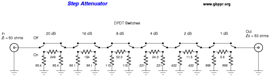
If BOTH ends must be constant, for at least 90 years there has been a standard plan, like the attached.
The plans in this thread give-up the constant Z both-ends to get *half* the number of switch actions. In audio we can usually do that. Gain (impedance changes) is cheap.
This particular plan is valued for 50 Ohms. Scaling to another standard is trivial.
For completeness:
If BOTH ends must be constant, for at least 90 years there has been a standard plan, like the attached.
The plans in this thread give-up the constant Z both-ends to get *half* the number of switch actions. In audio we can usually do that. Gain (impedance changes) is cheap.
This particular plan is valued for 50 Ohms. Scaling to another standard is trivial.
Attachments
> if I want Constant source impedance....,if I want to Constant output impedance,
For completeness:
If BOTH ends must be constant, for at least 90 years there has been a standard plan, like the attached.
The plans in this thread give-up the constant Z both-ends to get *half* the number of switch actions. In audio we can usually do that. Gain (impedance changes) is cheap.
This particular plan is valued for 50 Ohms. Scaling to another standard is trivial.
thanks for you sharing.would you please share how to calulate if both ends constant for the 100K/50K?
- Status
- This old topic is closed. If you want to reopen this topic, contact a moderator using the "Report Post" button.
- Home
- Amplifiers
- Pass Labs
- Constant impedance relay-resistor logarithmic attenuator