Yes. If you've got a 2SK170-BL then its datasheet guarantees the current will be somewhere between 6mA and 12mA, a range of 2.00x.Would tying the gate to the supply pin on an Sk170 count as a single part?
The E202 current regulator diode datasheet guarantees its current will be somewhere between 1.68mA and 2.32mA, a range of 1.38x.
Glad to see you here Pete!Using an improved CCS is wholly dependent on the topology it is used in.
Ranging from a "blameless' , where the CCS's are working with NFB in both
the LTP/VAS.
To something like the Groner TIS .... where the TIS does all the ripple cancellation.
CCS type (or lack of one) , has little effect here.
Or , an ultra high feedback circuit (Sansui) , where global NFB rules. No CCS
still gets you >-100db PSRR.
OS
I arrived here, looking for measured data about CCS temperature stability.
Measured temperature coefficients of Bjts vbe and Leds.
I am interested in these two:
Led + BJT chosen for tempo cancellation.
BJT + BJT for a well known negative tempo.
Super high source impedance is not that important. For most applications fairly high and constant is enough.
Measured temperature coefficients of Bjts vbe and Leds.
I am interested in these two:
Led + BJT chosen for tempo cancellation.
BJT + BJT for a well known negative tempo.
Super high source impedance is not that important. For most applications fairly high and constant is enough.
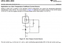
Temperature compensated LM334 requires 4 components, figure attached.
The more traditional Opamp, Precision VREF, MOSFET, and current sensing resistor requires 5 components if you allow ~4V drop across the current source; 7 components if you only allow yourself to drop < 400mV across the current source.
~
The more traditional Opamp, Precision VREF, MOSFET, and current sensing resistor requires 5 components if you allow ~4V drop across the current source; 7 components if you only allow yourself to drop < 400mV across the current source.
~
Attachments
MAX6162 voltage reference IC is ±0.1% tolerance and tempco is 5 ppm/°C ; qty=1 price is $2.89
Vishay Dale PTF resistor family is ±0.1% tolerance and tempco is ±10ppm/°C ; qty=1 price is $0.92
Microchip MCP6V26 opamp input offset error voltage is 2 microvolts ; qty=1 price is $1.61
Vishay Dale PTF resistor family is ±0.1% tolerance and tempco is ±10ppm/°C ; qty=1 price is $0.92
Microchip MCP6V26 opamp input offset error voltage is 2 microvolts ; qty=1 price is $1.61
I'll make my CCS for 1mA constant current with:
A cheap IR led ( a 50mA that do VF = 1.3v @ 20mA )
A 2N5551 with a 475 ohm emitter resistor. Very small parasitic cap, 160v range.
Biasing the led at 2.5mA ( with a 20k resistor to 50v ).
Bullet proof simple and cheap.
This will be good enough for my application, I bet I have better than 5% constant current over 0°C +60°C.
Last edited:
I was asking for measured data because I failed to find consistent data about Led and Bjt in data sheets or articles about temperature coefficients.
No luck, but running in circles on copy pasted unverified internet rehashed data.
Meanwhile, I hope I can get reliable data with LTspice and Spice models.
No luck, but running in circles on copy pasted unverified internet rehashed data.
Meanwhile, I hope I can get reliable data with LTspice and Spice models.
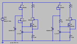
I just simulated a CCS made of two 2N5551
With 10k to 50v biasing, 147 ohm emitter resistance to get a 5mA output.
A constant 5ma source over 0.9v to 100v
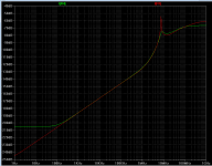
LTspice simulation results:
Ouput impedance is 5 Megohm.
Temperature stability is 0.5mA decrease over temperature increase from 10°C to 60°C
That is a TempCo = - 0.2% / °C
With 10k to 50v biasing, 147 ohm emitter resistance to get a 5mA output.
A constant 5ma source over 0.9v to 100v
LTspice simulation results:
Ouput impedance is 5 Megohm.
Temperature stability is 0.5mA decrease over temperature increase from 10°C to 60°C
That is a TempCo = - 0.2% / °C
This is not really a two-terminal CCS, unless you are ready to accept unpleasant tradeoffs.
Here are some examples of 2 wire CCS, some of which can be designed with a -0.3%/°C tempco:
Improved 2W current sources (II)
Here are some examples of 2 wire CCS, some of which can be designed with a -0.3%/°C tempco:
Improved 2W current sources (II)
What "unpleasant tradeoffs ?This is not really a two-terminal, unless you are ready to accept unpleasant tradeoffs.
The circuit I proposed is simple, costs about $0.40 is -0.2% / °C tempco, is 5 MegOhm output, is 140v able from 0.9v to 160v.Here are some examples of 2 wire CCS, some of which can be designed with a -0.3%/°C tempco:
Improved 2W current sources (II)
An interesting detail about using it as a temperature sensor: The temperature negative tempco comes from the transistor that is not at the output. That is the one to thermally bound to the device one wants to monitor.
The transistor at the output is responsible for a negligeable positive tempco ( 70 times less than the transistor doing the positive tempco ), so leave this one at ambient temperature ( on a small heatsink, if necessary. Its self heating can be hight and depends of the voltage output of the CCS ).
The sensing transistor has a very low self heating because of a very low power, which furthermore is constant over all output voltages of the CCS.
I only see advantages in the CCS made with 2 BJTs ( at posts #55 #57 ).
Last edited:
Your circuit is not natively floating or two-terminal, because of the auxiliary 50V supply tied to the ground.What "unpleasant tradeoffs ?
To make it 2W, you need to remove V1 and attach R1 to the collector of Q2.
Try it, and you will become aware of the tradeoffs this implies...
It is just the textbook 2-Q CCS, and its properties and limitations are very well knownThe circuit I proposed is simple, costs about $0.40 is -0.2% / °C tempco, is 5 MegOhm output, is 140v able from 0.9v to 160v.
- Status
- This old topic is closed. If you want to reopen this topic, contact a moderator using the "Report Post" button.
- Home
- Amplifiers
- Solid State
- Constant Current Source (CCS) For Audio Applications