Thanks for the reply Dave. I guess you and Roger were not there at the same time. Anyway, I'm learning but, like most, I'd like to get it as close to "right" as possible the first time. I've actually built several lines over the years and heard the things I am now learning more about thanks to people like you and the others here.
I've been trying to understand how numurous systems not designed with philosphies like CBT reportedly don't exhibit the lobing and high frequency problems as expected. Some like the IDS-25 don't even use seperate lines of HF Drirvers? Line arrays are also subject to the effects being discussed in the " 'Flat' is not correct for a stereo system ?" thread:
http://www.diyaudio.com/forums/multi-way/172806-flat-not-correct-stereo-system.html
Many people speak of rolling off the high freqs towards the ends of the array. What about the phase shift involved in useing these methods?
Sure, I could just copy someone elses succsessfull efforts and enjoy but, this is DIY. I'm just trying to put all or some of this knowledge together somehow for my next project.
Last edited:
We overlapped a year or two.Thanks for the reply Dave. I guess you and Roger were not there at the same time.
I've been trying to understand how numurous systems not designed with philosphies like CBT reportedly don't exhibit the lobing and high frequency problems as expected.
Remember there are two different "customers' for line arrays. In pro audio they are used for their high vertical coverage control. Listeners are always well into the far field. That is what the CBT is aimed at and where most of the line array research has gone into. People have come up with computer models and improved arrays both for one piece systems and for those who will stack a number of modules to create their own PA array. The second interest group is home audiophiles. For us, we aren't way in the far field enjoying the extreme directivity. We are in the nearfield enjoying the vertical uniformity. If your array is floor to ceiling then tapering will not improve it. For shorter arrays vertical uniformity is poor and various tapering schemes will greatly improve the array. My paper goes into the causes and cures for this: http://www.diyaudio.com/forums/mult...th-transducers-line-arrays-6.html#post2257395
Many people speak of rolling off the high freqs towards the ends of the array. What about the phase shift involved in useing these methods?
Level tapering is, of course, without phase shift. I have generally used frequency tapering only with very short arrays, such as 3 tweeter arrays for THX approval. In that case, first order rolloffs will give 45 degrees at the corner frequency, with no ill effects.
David S.
I really hate to hijack or be OT but since this is the most active Line Array thread: I guess my most purplexing question now might be: Is my planned array of 32223, 4" 8ohm drivers better as a power tappered system or as the outer drivers 1st order rolled off with baffle step compensation convieniently accounted for. I'm sure the next answer is: Set it up to audition both???
I currently have 24 peerless 830454 (P.E. 299-243) units but a few more wouldn't hurt. A few more might get me to the 70% of the floor to ceiling dimension. Any comments on the driver or the arrangement, or?
I was also planning on a side by side with a short ribbon line as yet undetermined. I really wanna hear it with no tweeters first but I realize I should be down to the 3-3.5" main driver dimension before I expect to get any results with no tweeter?
OB CBT?
I have a bunch of similar drivers my selves. My idea is to try to build a Open Baffle CBT.
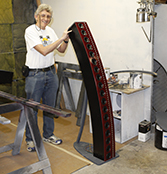
Picture from Don keeles website
Do you think it is a possible combination or will the radiation pattern from the OB-principal interfere with the CBT-principal?
I have 32 of the 69 cent 4 inch drivers from Parts-express buy out a while ago, and 96 of the Vansonic Veco 32KC08-1 tweeters.
(picture borrowed from mr.pink at HiFiForum.nu)
Am I barking up the wrong tree or could this become something interesting?
Kind regards
/Forsman
I have a bunch of similar drivers my selves. My idea is to try to build a Open Baffle CBT.
Picture from Don keeles website
Do you think it is a possible combination or will the radiation pattern from the OB-principal interfere with the CBT-principal?
I have 32 of the 69 cent 4 inch drivers from Parts-express buy out a while ago, and 96 of the Vansonic Veco 32KC08-1 tweeters.
An externally hosted image should be here but it was not working when we last tested it.
An externally hosted image should be here but it was not working when we last tested it.
(picture borrowed from mr.pink at HiFiForum.nu)
Am I barking up the wrong tree or could this become something interesting?
Kind regards
/Forsman
...
Do you think it is a possible combination or will the radiation pattern from the OB-principal interfere with the CBT-principal?
...
/Forsman
Hello Forsman,
even when assuming symmetrical drivers (front/rear radiation),
you will not get constant beam width and symmetrical radiation
for front/rear.
If you choose a narrow baffle, to avoid side (horizontal plane)
lobing in the midrange, i expect the efficiency of the dipole radiation
at low frequencies to be slightly inferior to a straight and tall baffle,
but that might not be such a problem since the relative "height shrinking"
may be moderate compared to a straight one ...
Low frequency efficiency will be inferior to the closed box approach anyhow,
because the closed box will act as a usual monopole at LF.
You will need a subwofer anyway and your concept will be restricted to
100Hz + or thereabouts.
What to to with the rear radiation ?
In free air maybe no problem, but in a living room that asymmetric
dispersion may be undesirable.
Damping the rear side of the drivers with absorbent material towards
higher frequencies might be a way to go.
I would have preferred a straight dipole line array with power tapering
(frequency dependent) but, if you find a way to "shape/absorb" the rear
radiation - why not. Maybe rear damping "some" of the drivers
is also a way to go, maybe the result without rear damping is OK within
your room ...
Rear radiation from fullrangers is typically falling above some Khz anyhow,
mostly in a non smooth but peaking manner ... some rear absorbtion
can tame that.
I see some "asymmetries" and a subwoofer needed, but not the idea
being "wrong" or "bad" as such. It is an "it depends" approach, which will
most probably need some tweaking and refinement (also room dependent).
edit: sorry i see you going 2-way anyhow. In case your tweeters are monopoles,
you will have just the usual -dipole/monopole- transition problem.
Nevertheless rear damping and well chosen crossover frequency might be
the relevant points in design/experimenting.
Kind Regards
Last edited:
I have a bunch of similar drivers my selves. My idea is to try to build a Open Baffle CBT.
Do you think it is a possible combination or will the radiation pattern from the OB-principal interfere with the CBT-principal?
In my experience the directional pattern of the drivers and the directivity of the array are fully independent matters. In that regard you should be able to create a line array with open back units and see the combination of the two polar patterns. This is just as you could use constant directivity elements and see a combination of the CD pattern and the array pattern.
When I was initially simulating arrays the software was pretty simplistic and assumed an omni radiating point for each element. All the simulations showed equal front and back radiation while the real measurements, of course, had considerable falloff to the back since the tweeters used were directional.
Since the CBT curves the plane of the upper elements will be slightly off from those of the lower units, but for the most part I think the CBT properties will still hold. To the rear will not be so good since the physical delay of upper units is reversed. If you cared about the "niceness" of back radiation you could use electrical dealy rather than physical. It would then work equally in both directions.
Still, you might ask yourself what you expect to get out of combining the two properties. Polarwise you will have high vertical directivity in the front, plus the inherent lateral dipole null along with strong backwards radiation. What is the expectation?
David Smith
I really hate to hijack or be OT but since this is the most active Line Array thread: I guess my most purplexing question now might be: Is my planned array of 32223, 4" 8ohm drivers better as a power tappered system or as the outer drivers 1st order rolled off with baffle step compensation convieniently accounted for. I'm sure the next answer is: Set it up to audition both???
I currently have 24 peerless 830454 (P.E. 299-243) units but a few more wouldn't hurt. A few more might get me to the 70% of the floor to ceiling dimension. Any comments on the driver or the arrangement, or?
I was also planning on a side by side with a short ribbon line as yet undetermined.
I found that level tapering made a big improvement with what I would call "mid length" arrays. At McIntosh that was the 16 element array that was about 1.2 meters long. The difference between standing and sitting was pretty strong and the level tapered XRT 24 was a dramatic improvment.
The long arrays of the XRT 20 and 26 type were, in the end, only 1.76 meters long but that was enough longer that your standing/sitting points didn't seem to be so different, so level tapering was less essential.
As to level tapering vs. rolling off outer units, think of it this way, level tapering can give you smoother polars, i.e. more uniform vertical response at a given frequency. Response roll off can give you constant directivity, ideally by shortening the line to half its effective length for every octave you go up in frequency. Unless you are willing to give a real progressive rolloff with multiple corner frequencies, I wouldn't expect good results.
Hope that helps,
David Smith
Thanks Dave, sounds like my original 32223 wiring plan would be a good first attempt. That would end up just over 1.3m I think. Not to much tapper on the outside 3 strings. I could also leave some extra on the top and bottom of the baffle and add a few latter if I thought I needed something else. Since constructing the unit this way would not rule out either method I might just stick with the 12/side arrangement for now and give it a whirl 
LineArray and speaker dave - Thanks for your comments!
I think I´ve understood that the back wave will be assymetrical but I´m not sure that it will be a problem. My living room is very long and the speakers will be placed in the middle. I think there will be at least 4 meters to the wall behind them.
I have looked at MJKs passive OB designs ant thought that I start of some were there. In that case the baffle will be 20 in wide. I´m not familiar with the phenomenon of wide baffles resulting in lobing in the midrange. Could you please elaborate on this or point me in a direction where I can read more?
I´ve thought of solving the lack of bass either by including drivers like Eminence Alpha 15 (or similar) or build a tapped horn. Of what I’ve read the bass from a tapped horn should be even better than from an OB. But then it is far more job to build a tapped horn instead of mounting one or two 15” drivers at each baffle.
I´m glad you think it´s a possible combo. To be honest I´m not positive what my expectations are. I think I´d like a speaker with:
Kind regards
/Forsman
I think I´ve understood that the back wave will be assymetrical but I´m not sure that it will be a problem. My living room is very long and the speakers will be placed in the middle. I think there will be at least 4 meters to the wall behind them.
I have looked at MJKs passive OB designs ant thought that I start of some were there. In that case the baffle will be 20 in wide. I´m not familiar with the phenomenon of wide baffles resulting in lobing in the midrange. Could you please elaborate on this or point me in a direction where I can read more?
I´ve thought of solving the lack of bass either by including drivers like Eminence Alpha 15 (or similar) or build a tapped horn. Of what I’ve read the bass from a tapped horn should be even better than from an OB. But then it is far more job to build a tapped horn instead of mounting one or two 15” drivers at each baffle.
I´m glad you think it´s a possible combo. To be honest I´m not positive what my expectations are. I think I´d like a speaker with:
- High sensitivity
- No interfering floor reflection
- Limited side wall reflection
- Symmetrical vertical, and if possible – lateral, polar patterns
- Esthetically pleasing design
and
- To experiment with interesting design theories and hopefully learn a lot
Kind regards
/Forsman
Are we spoiled for choice now?
If one wanted to build something like this or the Roger Russell equalized version using small full ranges full height what small 2 - 3 inch units would you use.
With the advent of cellphone and ipod docks there seem to be a huge range of speakers in this size group. Aurasound,Tangband, HiVi and I think Tympany come to mind. Fostex would be OK too but pricey. Price range seems to vary from about $12ea. to $35ea. Top end is a bit dear for 30 odd speakers each channel in a full length array but towards the bottom end it is no more expensive than one good mid range unit.
I guess with the cheaper ones the array would work from about 250Hz, maybe a bit less, upwards.
jamikl
For shorter arrays vertical uniformity is poor and various tapering schemes will greatly improve the array. My paper goes into the causes and cures for this: http://www.diyaudio.com/forums/mult...th-transducers-line-arrays-6.html#post2257395
I remember that paper when it came out. It was a nice bit of work. <golf clap>
...
I have looked at MJKs passive OB designs ant thought that I start of some were there. In that case the baffle will be 20 in wide. I´m not familiar with the phenomenon of wide baffles resulting in lobing in the midrange. Could you please elaborate on this or point me in a direction where I can read more?
...
Hello,
i have found a tutorial at John Kreskovsky's page
on OB polar dispersion, based on the
"two point source model":
Dipoles and Open Baffles
There must be also a nice picture on
Linkwitz Lab - Loudspeaker Design
but i currently cannot find it ...
As a rule of thumb, to avoid broadening of the
"figure 8" pattern and lobing, the baffle
diameter of a circular baffle has to be smaller
than 2 x d with d being the diameter of the driver.
To avoid side lobing baffle_width < 2 x d would
apply. A pistonic acting and front/rear symmetric
driver is assumed ...
Pistonic action ends above a certain frequency with
a given driver, as well as front/rear symmetry ends
due to spider/magnet/basket hampering the rear
radiation above a certain frequency range
(1-2 Khz for many fullrange drivers).
The rear "rolloff" is not very smooth often, but has
some "peaks and dips" usually.
Above that frequency range, where the driver
behaves pistonic and (fairly) symmetric, also
the polar dispersion in not predictable by the model
anymore and may get irregular although the above
size criterion is fullfilled.
In short: Even a fullranger mounted on a 2 x d or
narrower baffle will show side lobing in the highs.
But it will avoid side lobing in the midrange, as long
as it moves close to pistonic.
B.T.W. also vertical dispersion is affected by the drivers
acting non pistonic. Even prediction models for vertical
dispersion of arrays usually assume pistonic drivers.
Kind Regards
Last edited:
Hello,
<<bumped into server maintenance while editing ...>>
B.T.W. also vertical dispersion is affected by non-pistonic
motion of the drivers. Even prediction models for vertical
dispersion of arrays usually assume pistonic drivers.
As side lobing may have a fairly detrimental effect on
stereo imageing at varying listening positions, it makes
little sense to think about optimizing vertical dispersion
while neglecting dispersion in the horizontal plane.
Since the horizontal plane is the preferred plane in
which humans move, this is the "plane of prioirity"
to optimize IMO, at least for living room applications.
To have the frequency response balanced, even for
vertical angles, is important for people having "usual"
listening positions.
That means the range is from a small person sitting to
a tall person standing at "useful" listening distances.
If you manage to make a line array which performs
balanced at those positions - even with real drivers -
then you have achieved a practical result.
The relative vertical distance of real drivers membranes
in an array rises in case of non pistonic drivers, as the
effective cone area shrinks and the motion is more and
more centered around the voice coil joint.
The "constant beamwith" approach in a nearfield
line arrays depends on drivers which act really pistonic
AND which can be mounted real tight. Only multiway
approaches with small tweeters or real (stacked) line
sources are possible IMO.
That "acoustically close mounting" cannot be fullfilled
with any fullrange driver, since the "effective
membrane diameter" shrinks at high frequencies.
It cannot be mounted "acoustically close" for higher
frequencies, no matter how close you mount them ...
Kind Regards
Last edited:
Hi Forsman,
How do feel about the Vansonic? How does it sound at the top freq range? Do you recommend it?
Here you have listed the features of a dipole line array
- Elias
How do feel about the Vansonic? How does it sound at the top freq range? Do you recommend it?
96 of the Vansonic Veco 32KC08-1 tweeters.
An externally hosted image should be here but it was not working when we last tested it.
Here you have listed the features of a dipole line array
I think I´d like a speaker with:
- High sensitivity
- No interfering floor reflection
- Limited side wall reflection
- Symmetrical vertical, and if possible – lateral, polar patterns
- Esthetically pleasing design
- Elias
Thank you LineArray. I need some time to digest it.
It will take me some time to understand all of it but I´m trying.
Elias:
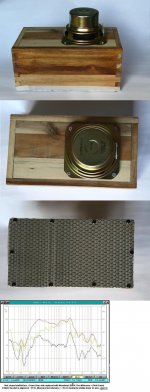
I cant go so far that I will recomend or advice against them. I have tried six of them, crossed over at 3000 an 2000 Hz, to a small MLTL and I think it sounds promising.
It will take me some time to understand all of it but I´m trying.
Elias:
I cant go so far that I will recomend or advice against them. I have tried six of them, crossed over at 3000 an 2000 Hz, to a small MLTL and I think it sounds promising.
A little but prommising test
/Forsman
An externally hosted image should be here but it was not working when we last tested it.
/Forsman
A little but prommising test
An externally hosted image should be here but it was not working when we last tested it.
/Forsman
Hi Forsman,
Where can I find (buy) the Vansonic drivers?
b
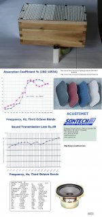
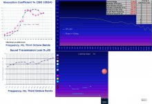
Ps: I have more than 500 of the 49 cent NSB:s, See the test results of an one driver experiment I made this summer for an semi open array to be placed near a wall:
Attachments
Hi Forsman,
`````````````````````minor snip``````````````````````````
Ps: I have more than 500 of the 49 cent NSB:s, See the test results of an one driver experiment I made this summer for an semi open array to be placed near a wall:
I bought a case of those for a Boy Scout project, and one of the other Dad's and I measured them against some Audax 4 inch drivers (cost: $49 each) and the NSB's actually had a better Frequency Response!
They're not a bad driver at all dispite the cost, although the flange around the driver could be a bit wider. A donut shaped flange made out of 1/8 inch masonite can actually take care of that and you would end up with a great eco-driver.
Best Regards,
TerryO
Last edited:
Hi Forsman,
Where can I find (buy) the Vansonic drivers?
b
Hi bjoro
Very interesting test. Will have a closer look at them when I have possibility.
You can buy the drivers from ELFA but I think it is much cheaper to buy them directly from the manufacturer. The only problem with that is that they only sell to companies and the smallest order they accepts is 500 pcs. But then we are talking about a completely different price. I had some contact with them and they are always answering and is very service minded.
Kind regads
/Forsman
Last edited:
- Home
- Loudspeakers
- Multi-Way
- Constant Beam Width Transducers line arrays