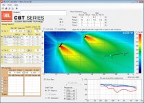
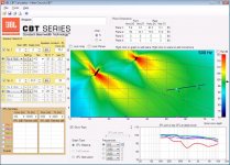
If we give up on the front of the seating area (maybe they get direct sound?), I can get great uniformity for all other seats. This uses your dimensions but pulled the balcony speakers forward, adjusts the angles and adds mild EQ to the two systems. I wasn't seeing much effect from the delay variable.
David
David
Attachments
Thanks Dave! Your version definitely improves coverage uniformity if we assume the front seats get a direct-sound boost.
I think Weltersys' point about echo wasn't so much in the direct field as the reverberant one--side spillage from the balcony array bouncing off walls a number of milliseconds after that of the front array. In your sim, the balcony array is -2dB wrt the front array, so if the delay echo is an issue, it starts 4dB higher than it would in my sim. In your experience, is that anything to worry about?
I think Weltersys' point about echo wasn't so much in the direct field as the reverberant one--side spillage from the balcony array bouncing off walls a number of milliseconds after that of the front array. In your sim, the balcony array is -2dB wrt the front array, so if the delay echo is an issue, it starts 4dB higher than it would in my sim. In your experience, is that anything to worry about?
The delay for the front was an error, is backwards. With delay on the back then I start to see some significance to the back point (gray point) and really good timing with about 22 to 24 msec (rear speaker delay). For other seating points it makes less difference implying they strongly see one system or the other rather than much overlap.
Side echos may or may not be a problem, but the delay of the balcony system will put the echo more in time with the front speaker and its echos, so I would assume that is a good thing. This program tells you about the direct field but knows nothing of the room's reverberation. Still, in the end you are increasing the direct sound so direct to reflected ratio and inteligibility must be improving, even if you are creating echoes.
The system is easy to optimize since you can see changes in real time and just hold down the various up and down arrows. You will see that each change has more effect over its group of seats (back speaker tilt over the back two points, etc.) so you can up and down the variable a couple of times until you think the uniformity is best. Ditto with system levels. Even with EQ you see that one EQ has more effect for certain seats and the other for the rest. I find this makes it all pretty easy to come to an optimum solution.
David
Once again, Dave, on behalf of our church, thanks for your help refining our speaker plan! ")
There are some structural things that these sims can't account for, such as the wall extending down from the front of the balcony, but this gives us a great starting point to begin fine-tuning in the real world.
Bill
There are some structural things that these sims can't account for, such as the wall extending down from the front of the balcony, but this gives us a great starting point to begin fine-tuning in the real world.
Bill
At 4K the array has good directional control, the interaction will be well behaved (as long as temperature and humidity remain constantIf we give up on the front of the seating area (maybe they get direct sound?), I can get great uniformity for all other seats. This uses your dimensions but pulled the balcony speakers forward, adjusts the angles and adds mild EQ to the two systems. I wasn't seeing much effect from the delay variable.
David
) between the mains and balcony delay at that particular frequency.At lower frequencies, the array becomes progressively omni directional, rear waves from the delay will have progressively greater negative effect at the very frequencies that generally are less affected by room acoustical treatment.
Try your sim at frequencies from 100- 500 Hz, even the direct sound from the mains/delay interference zone will not be pretty, add in LF reverb and "the delay variable" becomes rather large.
Of course, sims are only 2 dimensional while acoustical spaces are three dimensional....
Art
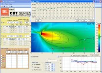
Response curves for the sims are for all frequencies. Only the color polar map is for a chosen frequency. Response curves show the summation is very well behaved across the board.
From previous sims I've done on this, as long as the delay is adequate to deal with the physical delay between the speakers it works well. It can be greater by some amount to deal with temperature effects and show no problems.
Download the software and try it yourself.
David
From previous sims I've done on this, as long as the delay is adequate to deal with the physical delay between the speakers it works well. It can be greater by some amount to deal with temperature effects and show no problems.
Download the software and try it yourself.
David
I'd certainly be interested in seeing the "well behaved" color polar map is for the frequencies from 100- 500 Hz, though not enough to download and become familiar with another program that I would probably never use again.Response curves for the sims are for all frequencies. Only the color polar map is for a chosen frequency. Response curves show the summation is very well behaved across the board.
Perhaps the OP, having a vested interest, will investigate and post those "well behaved" polar maps at lower frequencies.
Art
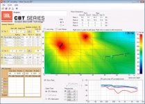
I said the response curves from seat to seat were well behaved, as you can see they are in the previous plots. The lower frequency polars are also well behaved but with some broadening of response and a pick up of rear radiation.
I don't know why you are so antagonistic towards the topic. As to the 15 minutes it would take to download and familiarize yourself with the program, well....
David
I don't know why you are so antagonistic towards the topic. As to the 15 minutes it would take to download and familiarize yourself with the program, well....
David
Attachments
Yesterday I measured our church sanctuary, and I found that my earlier estimates were a bit off. The lower seating area is shallower than I estimated, and the balcony is lower. I also determined I could hang the front array lower and farther back than I had first thought.
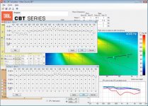
The good news is that all the changes are for the better. Plugging the new measurements into the CBT sim, I can now get good coverage everywhere (except the front row) with a single front array. This sidesteps the echo issue and saves us a bit of money, too.
BTW, by moving the array back over the platform, am I creating a feedback problem?
Attachments
Last edited:
David,I said the response curves from seat to seat were well behaved, as you can see they are in the previous plots. The lower frequency polars are also well behaved but with some broadening of response and a pick up of rear radiation.
David
Having previously spent some hours downloading and becoming marginally familiar with operation of Meyer’s MAPP room sim, I think you overestimate my ability to easily pick up new programs quickly
.Thank you for taking the time to post the plots of the JBL speakers at different frequencies.
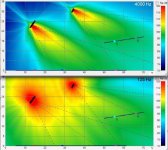
The 4000 Hz plot clearly shows a defined, uniform ( within a few dB) pattern of coverage specifically covering the audience, with as much as 25 dB less level in areas that would result in reflected sound (reverb).
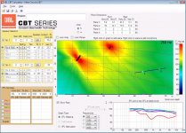
The 125 Hz plot clearly shows the pair of arrays have virtually no pattern control at lower frequencies, most of the wall and ceiling areas are hit with a SPL louder than in the desired coverage area.
“Some broadening”, in this case, means on the order of a 35 dB difference in off axis response between the two plots.
Thank you for sharing with us what “some broadening” looks like, as they say, "a picture is worth a thousand words" (or perhaps 35 dB)
.Art
Attachments
Last edited:
Most likely, yes, as even cardioid microphones are progressively omnidirectional at low frequencies where the array has progressively less pattern control. The closer the array to the microphone, the less gain before feedback.BTW, by moving the array back over the platform, am I creating a feedback problem?
As well as picking up the direct level of the array, the microphone will also pick up the reflected low frequency sound from the array, compounding room LF reverb.
You can compare the microphone off axis rejection at lower frequencies with the array's LF response to help determine how much of a problem moving the array closer to the microphone location will cause.
Art
Absolutely.The longer the array, the tighter the pattern in the lower mids.
A long array does not seem to be under consideration here, so pattern control at lower frequencies is compromised.
FWIW, the JBL CBT70J + CBT70JE extender under consideration is about 55" long.
From the CBT FAQ:
CBT 70J + CBT 70JE – The addition of the extension cabinet doubles the height of the array, extending the pattern control down to 400 Hz – covering the voice range – while doubling the power handling, increasing the sound level capability by 6 dB and extending the frequency response down to 45 Hz.
Last edited:
Most likely, yes, as even cardioid microphones are progressively omnidirectional at low frequencies where the array has progressively less pattern control. The closer the array to the microphone, the less gain before feedback.
Essentially, the bottom of the array will hang about 9 feet directly above the head of the presenter (15 feet above the floor). This should be okay, right? Or is it better generally to hang it several feet ahead of the presenter?
Mics will be a mix of those over-the-ear face mics and cardioid handhelds.
Last edited:
David,
“Some broadening”, in this case, means on the order of a 35 dB difference in off axis response between the two plots.
Thank you for sharing with us what “some broadening” looks like, as they say, "a picture is worth a thousand words" (or perhaps 35 dB)
Art
And I assume you have another product in mind, of similar size, that has great pattern control at 125 Hz?
David
The good news is that all the changes are for the better. Plugging the new measurements into the CBT sim, I can now get good coverage everywhere (except the front row) with a single front array. This sidesteps the echo issue and saves us a bit of money, too.
BTW, by moving the array back over the platform, am I creating a feedback problem?
That looks pretty good Bill. Looks like you've mastered the technique.
If you are curious about the feedback issue than put another measurement point where you think the microphone will be and keep an eye on the difference between that level and the listener levels.
In spite of noise to the contrary, I don't recall ever hearing a PA system feed back at 125 Hz. Not impossible but...
David S.
- Home
- Loudspeakers
- Multi-Way
- Constant Beam Width Transducers line arrays