This should work but will be a lot of work to make shure you dont have ground loops and other hum & noise , in theory it works but dont do it unless you are a pro.
yes, that will work, i have done it before.....you can start at the secondary side making the connections as shown, then monitoring primary voltaqe for correct phasing...
Last edited:
In the option of Tony of post 61 one might connect the appropriate AC-voltage to the secondary and measure with a multimeter whether the primary will yield about 240V. If not, the primary might not be wired in the correct phasing.
By wiring the two secondary windings in parallel, the two transformers will be loaded equally. In the first attached schematic the option of Tony of post 61 is, for example, represented with a choke input rectification. The second, with the secundaries in parallel without a center tap, is an example with a rectification bridge and a choke input.


By wiring the two secondary windings in parallel, the two transformers will be loaded equally. In the first attached schematic the option of Tony of post 61 is, for example, represented with a choke input rectification. The second, with the secundaries in parallel without a center tap, is an example with a rectification bridge and a choke input.
No, it has an AC component and a DC component, frequency isn't relevant.I would say rectified AC has a frequency component. Yet it is still DC.
Suppose you have a half-wave rectified AC voltage where the 1/2 cycles are positive going. View that on a DC coupled scope, with the display adjusted so that the base-line of the waveform is set to the centre line on the graticule, if you then switch the scope to AC coupling, the waveform will move down by an amount equal to the DC component of the waveform. What you are then seeing is an AC waveform, albeit a non-sinusoidal one, with the DC component removed.
Regards,
Dave.
Any waveform have:
a minimum value
a maximum value
a mean value
a RMS value
On a plain DC signal ( no waveform ) all those value are equal.
If there is a waveform you may have up to 4 different values.
If on a graphic the wave form ( voltage or current ) cross the zero axix it is an alternating signal ( AC waveform ).
Crossing the axis means having a current that flows a part of the time in one direction and a part of the time in the opposite direction.
Crossing the axis for a voltage mean that polarity revese evry time the waveform cross the axis.
If on a graphic the wave form ( voltage or current ) does not cross the zero axix it is a direct signal ( DC waveform )
There is no change in polarity or in the direction of the current.
A DC signal may be a pulsating current ( rectifers produce pulsating curret )
The technic propose by AMRAD is a standard way of measuring the mean value of a wavewfom , also known as the DC level of the wave by measuring the displacement of the waveform on a scope when you switch from DC coupling to AC coupling.
Perhaps duty cycle is the more precise term.No, it has an AC component and a DC component, frequency isn't relevant.
Correct.Suppose you have a half-wave rectified AC voltage where the 1/2 cycles are positive going.
Positive going. Not negative going. Not alternating. Not alternating current.
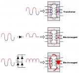
Just for fun, here is the simulation of the half-wave rectifier feeding the primary of a 115V 500VA transformer with a 230V mains.
The "normal" situation is also included for reference.
The transformer's model is complete and realistic, and includes leakage inductance, core's saturation, etc.
The first pic shows the primary currents, and the voltage after the diode.
In the normal case, the rms is under 3.5A against more than 15A with the rectifier.
The transformer tries to recreate a balanced AC voltage despite the presence of the diode.
The second pic shows the secondary voltages: 50V for the normal circuit, and almost the double for the other.
In summary: not something to try for real, although the results are less brutal than I had figured
Attachments
- Status
- This old topic is closed. If you want to reopen this topic, contact a moderator using the "Report Post" button.
- Home
- Amplifiers
- Solid State
- connecting two 110v amplifiers in series on 220v mains