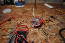
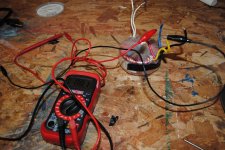
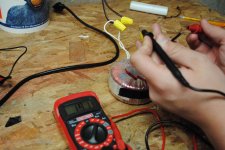
I am trying to get a set of chipamp 3886 boards running, but am having some confusing issues with my transformer. I bought it from Apex Jr a while back, and I believe it is dual 24v, but I'm not 100% sure. It's something around that voltage. The issue I am having is that when I plug it in, I very little output, except between black and yellow. I have not been able to read any resistance, from anywhere on it. Attached are pictures of my measurements.
Could someone please give me some sort of direction of what to try next? I'm stumped.
I have more pics/measurments if needed, these are just a sample.
Could someone please give me some sort of direction of what to try next? I'm stumped.
I have more pics/measurments if needed, these are just a sample.
Attachments
That's what I was thinking too, but the readings don't agree. I'll post more pics shortly, I'm just finishing some work on my car that I need to get done, as it looks like rain is on the way.
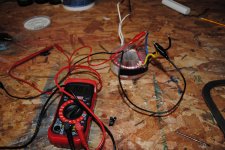
As for the label, I'll post a pic, but it doesn't give much information.
As for the label, I'll post a pic, but it doesn't give much information.
Post some more pics. I'd say you have two secondaries (independent): one between yellow and black, and the other between red and blue
Are you sure the meter is working correctly? You should be able to get continuity between two pairs on the secondary windings. I'd also check the primary for continuity.
Just noticed the NON-INSULATED CONNECTIONS to the primary, that is a NO-NO! I recommend you immediately un-plug from the mains and put wire nuts or at least electrical tape over them. Lethal voltage is nothing to take lightly.
Mike
Just noticed the NON-INSULATED CONNECTIONS to the primary, that is a NO-NO! I recommend you immediately un-plug from the mains and put wire nuts or at least electrical tape over them. Lethal voltage is nothing to take lightly.
Mike
Last edited:
yes, safety first......
if that was mine, i will proceed to check it this way..
1. with a dmm set to read continuity audibly, i will check to see
which coils and label them or twist them to signify they are one coil,
2. resistance check to see dc resistances to more or less gauge which
is primary and which are secondaries.
3. having identified the coils, i will get a low voltage ac source such as a filament
transformer and inject say 6 volts onto the coils with lowest dc resistance,
then measure the voltages in the other coils...
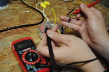
Fixed it! That was just a quick connection for testing, which I was lazy on, but wire nuts have now been added. And about the meter.... I almost don't want to post this it is such a stupid mistake....
I didn't realize that the red plating on the copper wires was insulating them, and preventing accurate readings. After trying a continuity check for the third time, I noticed a real quick beep when I touched the top of the wires (where there was bare copper). After filing to bare copper on all the wires, I'm now reading much more appropriate voltages.
Can you tell I'm a beginner?")
I didn't realize that the red plating on the copper wires was insulating them, and preventing accurate readings. After trying a continuity check for the third time, I noticed a real quick beep when I touched the top of the wires (where there was bare copper). After filing to bare copper on all the wires, I'm now reading much more appropriate voltages.
Can you tell I'm a beginner?
Are you sure the meter is working correctly? You should be able to get continuity between two pairs on the secondary windings. I'd also check the primary for continuity.
Just noticed the NON-INSULATED CONNECTIONS to the primary, that is a NO-NO! I recommend you immediately un-plug from the mains and put wire nuts or at least electrical tape over them. Lethal voltage is nothing to take lightly.
Mike
*NEW* Measurments
Here are my new measurements, after finally figuring out how to properly measure....
Continuity:
White-White
Red-Yellow
Black-Blue
Voltage:
White-White: about 120v
Red-Yellow: 26.8v
Black-Blue: 26.8v
Blue-Red: 15.8v
Yellow-Black: 19.1v
So from this I understand this is a dual 26.8v transformer. What I don't understand are the last two voltages I posted. There is no continuity between those wires. Is the voltage there okay?
Thanks again for your help everyone, there is definitely a learning curve to this!
Attachments
Awesome, thanks! Time to get my amp working!
it's a dual 24 volt traffo alright...
voltages measured on adjacent windings do not matter,
you are not getting any current out it....
the 26.8 volts no load will drop to 24v when rated current is drawn...
- Status
- This old topic is closed. If you want to reopen this topic, contact a moderator using the "Report Post" button.
- Home
- Amplifiers
- Power Supplies
- Confused with Toroid Transformer