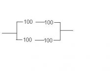
You really only need a single 100 ohm resistor, almost no current flowing through the screen in triode connection, but what you have done is ok.
Have you measured the voltage present on pin 5? There really shouldn't be much more than a couple of hundred millivolts max, and I'll bet that isn't the case here. Next short pin 5 directly to ground and remeasure the cathode current. (For safety shut the amp off to do this then repower and measure the cathode current.) Please post both cathode voltages indicating which is which, as well as the grid voltage across the 250K resistor.
Also please post the voltages measured at pins 3, 4, and 5 as well as any resistance values measured. (unpowered)
Um, also check your volt meter with a low voltage supply if available.
Who made your EL34?
This problem is so bizzarre.. I am sure once you find the problem we'll all breath a sigh of collective relief..
Edit
This sounds like something is miswired, or dead. Like an open (or wrong valued) grid resistor. It could also be bad tubes, but this is unlikely. I would agree with Kevin to measure (and post all of the DC voltages on the output tube with the negative meter lead grounded. It would be a good idea to measure the actual filament voltage (meter on AC, one lead on pin 2 and the other on pin 7). The grounded grid test that Kevin mentioned is a good idea too.
Is there someone who has an EL-34 amp that could try your tubes to see if they got damaged somehow? Even a guitar amp. The output stage of my EL-34 amp is almost identical to yours, and it has been cranking along since the day I finished it. I pulled out the JJ EL-34's this weekend and put in some cheap 6L6's for some transformer torture testing (big Hammond VS big Edcor showdown).
I just remembered something else. An EL-34 needs to have a wire connecting pin 1 (g3) to pin 8 (K) this is done internally for all of the other octal audio pentodes. If pin 1 is left unconnected it could cause the symptoms that you have. Check pin 1 first!
Yes this is true, but the small metal film ones that DigiKey sells function like heavy metal fuses. You play Metallica at full tilt and they blow! I zapped 3 of them, then I switched to 1 watt carbon film, no more blown resistors.
Is there someone who has an EL-34 amp that could try your tubes to see if they got damaged somehow? Even a guitar amp. The output stage of my EL-34 amp is almost identical to yours, and it has been cranking along since the day I finished it. I pulled out the JJ EL-34's this weekend and put in some cheap 6L6's for some transformer torture testing (big Hammond VS big Edcor showdown).
I just remembered something else. An EL-34 needs to have a wire connecting pin 1 (g3) to pin 8 (K) this is done internally for all of the other octal audio pentodes. If pin 1 is left unconnected it could cause the symptoms that you have. Check pin 1 first!
You really only need a single 100 ohm resistor
Yes this is true, but the small metal film ones that DigiKey sells function like heavy metal fuses. You play Metallica at full tilt and they blow! I zapped 3 of them, then I switched to 1 watt carbon film, no more blown resistors.
Alright here we go, I am copying down these measurements as I am taking them
Votlmeter reading across a 9v battery: 9.31v
testing resistances (amplifier not on)
Pin 1/Pin 8 to ground 511 omhs
from Pin 1 to pin 8 .1 ohms
from Pin 3 (plate) to ground: Infinity
Pin 4 (G2) to ground: Infinity
Pin 5 (G1) to ground: 251.1Kohms
Power on: waiting for tubes to heat up
Voltage across each EL34 Heater (pin 2 to pub 7): 3.399V AC (WTF?)
Tony Bennett Playing (but it sounds like hes underwater!)
Unsafe to measure voltage across 6aq8 (pin 4 to pin 5)
Voltage across pin3/4 417v DC (not enough voltage drop to warrent different readings)
Voltage across pin 5L ~12mv DC
Voltage drop across cathode resistor 4.5v
current ~9ma
Well it should be clear by now that the heater voltage is not nearly enough!
I hope the my wireing is at fault, and not my power transformer, as one is far easier, and cheaper to fix than the other
Yeah that low filament voltage would cause the sorts of symptoms you are seeing. Another clue would be a very dull filament glow.
No chance these were wired in series accidentally? The other thing to check if the filament winding has a center tap is whether or not this is connected in error to your tube filaments and the end which should be going to your filaments is instead connected to ground, left open or connected to the filament bias voltage network if present. Believe it or not I have done just this on an old transformer with faded wires.
No chance these were wired in series accidentally? The other thing to check if the filament winding has a center tap is whether or not this is connected in error to your tube filaments and the end which should be going to your filaments is instead connected to ground, left open or connected to the filament bias voltage network if present. Believe it or not I have done just this on an old transformer with faded wires.
Yep, that's it. Just use the two green wires and ground the green/yellow wire.
One other possibility would be to use the cathode bias from one channel to elevate the filament winding, and since this should be essentially pure dc given the 1000uF caps you are using this might result in an even quieter amplifier. (Connect the green/yellow wire to one of the output tube cathodes.) Note this shouldn't cause any problems but if the amplifier suddenly exhibits some low frequency instability suspect this first.
One other possibility would be to use the cathode bias from one channel to elevate the filament winding, and since this should be essentially pure dc given the 1000uF caps you are using this might result in an even quieter amplifier. (Connect the green/yellow wire to one of the output tube cathodes.) Note this shouldn't cause any problems but if the amplifier suddenly exhibits some low frequency instability suspect this first.
Plate dissipation= 18.5 watts!
Actually the cathode current is the sum of the plate current and the screen current. So the plate dissipation is probably 16 or 17 watts. You could try a slightly higher current if you think that you could use a little more power.
Now that you have it working, listen to it for a while play several CD's and get a feel for the type of music that strains the amplifier. Listen for certain musical passages where the amplifier has trouble. I find a female vocalist or a nylon stringed guitar that is covered by heavy bass will find intermodulation distortion. The voaclist seems like it is "chopped up by the bass". I have about 5 or 6 musical "tests" that I always use to test modifications.
After you have learned the amplifiers behavior, then you can try a few experiments. The simplest is to try the 5 K tap on the output transformer. This will usually offer less power than the 2.5 K tap, but better sound quality.
Another would be to re - connect the cathode feedback. The amp should lose some gain when you do this (more volume control required for the same loudness). If it gets louder or rudely oscillates, you have the transformer phasing reversed. I find that cathode feedback adds a lot to the 125CSE's bottom end.
You could also benefit from some more current. Each transformer will have an optimum current (where it produces the lowest distortion). You will find that your plate voltage will drop slightly as you increase the current. Calculate the dissipation from the voltage difference between the plate and cathode (times the tube current). I would try to keep it under 25 watts, although I have been known to violate these rules.
I am currently running some $4 6L6GC's at 35 watts in my amp. I can turn off the room lights and watch the blue glow dance to the music. There is some orange glow on the plates also. It goes away on loud music, and reappears on soft music. This is NOT recommended for tube life, but I am stress testing a few things!
tubelab.com said:
Actually the cathode current is the sum of the plate current and the screen current. So the plate dissipation is probably 16 or 17 watts. You could try a slightly higher current if you think that you could use a little more power.
Now that you have it working, listen to it for a while play several CD's and get a feel for the type of music that strains the amplifier. Listen for certain musical passages where the amplifier has trouble. I find a female vocalist or a nylon stringed guitar that is covered by heavy bass will find intermodulation distortion. The voaclist seems like it is "chopped up by the bass". I have about 5 or 6 musical "tests" that I always use to test modifications.
After you have learned the amplifiers behavior, then you can try a few experiments. The simplest is to try the 5 K tap on the output transformer. This will usually offer less power than the 2.5 K tap, but better sound quality.
Another would be to re - connect the cathode feedback. The amp should lose some gain when you do this (more volume control required for the same loudness). If it gets louder or rudely oscillates, you have the transformer phasing reversed. I find that cathode feedback adds a lot to the 125CSE's bottom end.
You could also benefit from some more current. Each transformer will have an optimum current (where it produces the lowest distortion). You will find that your plate voltage will drop slightly as you increase the current. Calculate the dissipation from the voltage difference between the plate and cathode (times the tube current). I would try to keep it under 25 watts, although I have been known to violate these rules.
I am currently running some $4 6L6GC's at 35 watts in my amp. I can turn off the room lights and watch the blue glow dance to the music. There is some orange glow on the plates also. It goes away on loud music, and reappears on soft music. This is NOT recommended for tube life, but I am stress testing a few things!
My 125CSE says 60ma on it, is that the optimum point? or is that the point at which saturation begins?
Honestly, I might boost the current a little, but the truth is that i need to just see how I like the sound over a week or two, the bass sounds like it looses controll sometimes.
So then if I increase the plate dissipation then I would get more power before clipping occurs, right?
I love the sound, the guitar solo at the begining of Wish You Were Here sounds like it never has before, I can only imagine what a 300b, or 2a3 set-up would sound like
the bass sounds like it looses controll sometimes.
Part of this is from the use of a "smallish" output transformer. Cathode feedback will help "tighten up the bass" by improving the frequency response and lowering the output impedance.
My 125CSE says 60ma on it
That is the recommended maximum current. This is usually based on saturation effects. I have run 125CSE's up to 80mA but I think they work best around 60mA. You may think different. This depends a lot on your speakers, and choice of music. Music with a lot of bass (Pink Floyd) will use up more of the magnetic headroom in the transformer, so sometimes you will get better results with slightly less current.
So then if I increase the plate dissipation then I would get more power before clipping occurs, right?
In most cases, yes. It depends on the load that the tube sees, which again depends on the tap you are using (2.5 K will give the most power, and wants more current) and the actual impedance of your speakers.
With all of that out of the way, I seem to prefer a lot of current (too much sometimes) with cathode feedback for music like Floyd. DSOM will really test an amp!
Its funny you should say that! as I busted out my SACD of The Dark Side of the Moon, and let it flow, (I never see turning up the volume as forcing something out, I see it was letting it free!) I listened to it all the way through on Stereo Mode. It really only had alot of trouble handling the loud parts of Us and Them. The time change in money (from 7/4 to 4/4) almost had trouble, but the bass seemed under controll, just barely.
the way I see it, I can already push the amp into hard clipping, so whats the point in not putting in Cathode feedback, or rasing the primary impedance? other than personal taste in the sound. or will clipping start at the same place reguardless?
Any changes will be made next week, as I come up with a more complete list of likes/dislikes
by the way: this amp loves Tommy, but it had a little trouble with The Who by Numbers
At this point you are probably limited by two things. Clipping and transformer saturation. There is not much you can do about saturation except for using a bigger OPT. If you decide down the road to upgrade the transformers, consider using one that has an Ultralinear tap. This will let you use Ultralinear mode for more power, and triode mode when you want the best possible sound. Ultralinear is supposed to be " the advantages of triode mode with the power of pentode mode". I find that it is a compromize, but with CFB, not a bad compromize. Going back to pentode mode will give you more power, but the bass will really "lose control". I tried it, and even with CFB, didn't like it.
The clipping point will not be changed by cathode feedback. It will afford improvement up until the amp clips. Changing the impedance tap will change the clipping point, but 2.5 K is probably the point that will give the most power. Raising the current slightly will raise the clipping point, and may lower the output impedance, which usually helps with the bass.
While I was typing last nights reply, I had Dark Side cranked up to the max. The only light on in the room was the glow from my laptop, and the tubes. The blue glow dances around on the glass. With 15 inch speakers and 11 pound output transformers, the only problem I have with bass is my neighbors complaining.
tubelab.com said:At this point you are probably limited by two things. Clipping and transformer saturation. There is not much you can do about saturation except for using a bigger OPT. If you decide down the road to upgrade the transformers, consider using one that has an Ultralinear tap. This will let you use Ultralinear mode for more power, and triode mode when you want the best possible sound. Ultralinear is supposed to be " the advantages of triode mode with the power of pentode mode". I find that it is a compromize, but with CFB, not a bad compromize. Going back to pentode mode will give you more power, but the bass will really "lose control". I tried it, and even with CFB, didn't like it.
The truth is that I only have an 8 watt OPT with the 125Cse, so it seems that running in UL mode would prove to be expensive but it just might be worth it, But I think next week I will definatly put CFB back on.
While I was typing last nights reply, I had Dark Side cranked up to the max. The only light on in the room was the glow from my laptop, and the tubes. The blue glow dances around on the glass. With 15 inch speakers and 11 pound output transformers, the only problem I have with bass is my neighbors complaining.
Was this with a Simple SE amp running in UL mode? and what tube was in it?
Was this with a Simple SE amp running in UL mode? and what tube was in it?
Yes. UL with cathode feedback. I was testing two different types of large output transformers. To get maximum power, I removed the EL-34's (they are too nice to abuse, and I only have 4) and put in some cheap 6L6GC's that are available for about $4 each on Ebay. I then lowered the cathode resistor to 438 ohms (2 K ohm in parallel with the 560 that is on the board). This puts the current at almost 80 mA. With 430 volts across the tube it is almost glowing (dull orange glow barely visible with the lights off). I can get almost 15 watts under these conditions. I don't know how long the poor tubes will last like this, but this pair has already lived a hard life in a Fender Bandmaster, and they still rock!
I have used 125CSE's in this amp and there were definite limitations to the bass. They are reasonably efficient transformers though so you are likely to lose some power (1/2 to 1 watt) by switching to larger transformers.
I am planning to offer amplifier kits based on the SimpleSE later this year, so I have been doing a lot of transformer testing. For a budget amp I will use the $18 Edcor. It sounds similar to the 125CSE, except that it is cheaper and has a UL tap. I haven't decided on which transformer to use in the better amp kits yet. I have posted the test results for the big transformers on my web site, and the results for the smaller transformers will be added as I have time to test them.
Your amp should be able to run 6L6GC's, EL-34's, KT-88's and 6550's by only changing the cathode resistor. I find that the JJ EL-34's have the best sound per dollar, although I am amazed by the $4 6L6GC's. 6550's make the most power and have the best bass, but they are not cheap. I won't subject them to torture testing.
- Status
- This old topic is closed. If you want to reopen this topic, contact a moderator using the "Report Post" button.
- Home
- Amplifiers
- Tubes / Valves
- Confused by the numbers