Hello
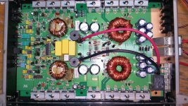
I received an HD1200 model concept amplifier.
It has an intermittent fault. It goes into protection mode on some occasions when applying remote tension.
It does not always enter protection mode, sometimes it works normally.
I Compare voltages of TL494 and LM393. When in protection mode and normal. In those measurements I do not have considerable variations.
Where if I have variable voltages measurements in IC 4080.
Here I put them:
POWER ON normally
1:41.7
2:11.97
3: .017
4:.000
5:5.98
6:5.85
7:5.89
8:5.19
9:5.24
10:41.7
11:35.8
12:30.55
13:5.66
14: .001
15:11.97
16:11.97
17: .002
18:5.68
19:30.51
20:35.7
IN PROTECT MODE :
1:11.43
2:11.97
3:11.46
4: .000
5: .004
6:5.83
7:10.94
8:5.19
9:11.70
10:11.44
11:9.00
12:9.00
13: .000
14: .000
15:11.97
16:11.97
17: .000
18: .000
19:9.01
20:9.00
I do not understand the operation of the 4080 well so I ask for help or a suggestion
Thanks for attention
Attachments
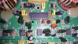
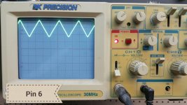
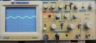
For the second image, if you had the scope set to 2ms, adjust the trigger level to see if you can get it to lock. You may have to remove the solder bridge to get an audio signal to pass. If the op-amp doesn't have a resistor connected between pins 1 and 2, you may need to connect a 10k resistor between those two pins to give it some local feedback.
This is all to be done with the 4080 out of the amp.
This is all to be done with the 4080 out of the amp.
Take the 4080 out of the circuit
Install a 10k resistor between pin 1 and 2 of U7
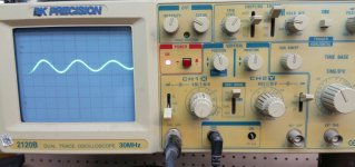
I checked each output fet 3710 and the 2 pairs of 7815 and 7915 with small lugs to verify that they are not broken from their terminals.
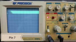
The measurements is with a tone of 110hz
Install a 10k resistor between pin 1 and 2 of U7
I checked each output fet 3710 and the 2 pairs of 7815 and 7915 with small lugs to verify that they are not broken from their terminals.
The measurements is with a tone of 110hz
Attachments
Are the output FETs original?
If so, did you lift them off of the heatsink so you could move the body of the FET side to side (watching carefully where the leg enters the body for movement)?
If you power up repeatedly, does the DC level always go back to where it is in the two photos?
If you push on the board with a non-conductive probe, does the DC level of either signal ever change?
Are the output FETs original?
If so, did you lift them off of the heatsink so you could move the body of the FET side to side (watching carefully where the leg enters the body for movement)?
If you power up repeatedly, does the DC level always go back to where it is in the two photos?
If you push on the board with a non-conductive probe, does the DC level of either signal ever change?
# 1 Yes, the fets are original. The only thing I change is the 4080
# 2 Yes, I also took off the heatskin fets and made movements to know if they have any problems in their terminals.
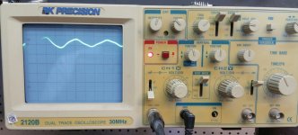
# 3 I managed to capture a picture of the measurement when starting the amplifier
# 4 I push the PCB board hard and I do not get rare measurements.
The client tells me to have more amplifiers of the same model with the same fault symptom.
It will be a factory defect .....?
Attachments
- Status
- This old topic is closed. If you want to reopen this topic, contact a moderator using the "Report Post" button.
- Home
- General Interest
- Car Audio
- Concept HD1200 intermittent protection mode