Banfi T. said:In theory a current source or a symmetrical stage would mean infinite load and thus infinite open loop gain, wich is not the case. ( I mean "in theory" here the state where I am now.) At least I never saw any book in wich the open loop gain were calculated, (Including JLH's book.) But for me it would be very important, beacuse without knowing this I can just handle the situation if I think of the whole network as an OPAMP, and what I have to calculate is the feedback network. I fear with this knowledge it is better to use OPAMPS.
The thing you ask about is what is the max "resistance" an emitter grounded stage can produce. A single transistor have max "output resistance" = 10 -50 kohm (depending on current, and other things), With a cascode you can reach 0,5-2 M ohms. With 100 ohm emitter resistance you can get 5000-20000 in gain.
Banfi,
Why do you care what the dc open loop gain is? This is very difficult to estimate.
When considering NFB the important thing is usually what the phase lag is when the open loop gain is unity (including feedback dividers, etc.).
Think about it in this way and it will make more sense.
Also, I have mentioned this in one or two other threads, it is not really meaningful to think of a darlington or a CFP or a compound darlington having an intrinsic o/p impedance . It is more meaningful to think of these as beta devices. They divide the impedance of the source that drives them.
I would also be careful about stability red-herrings regarding CFPs and darlingtons. The problems described are often due to other aspects of the circuits being tested and not some intrinsic problem with any particular topology. I think PMA's results reflect this. Think about the current paths and ask yourself what the true differences are between these topologies.
BAM
Peranders,
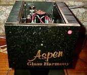
The Zout of my Glass Harmony SE stage using a bipolar/mosfet CFP is 38 milliohms, measured at 1KHz, 40Vpp into 8R. Up to clip, the sensation of power on just about any speaker is monomental. My AKSA 100W Class AB struggles to give an impression of power like the Glass Harmony, and the AKSA is often said to sound like a 200W amplifier in this regard.
I believe the Zout is dominated by the Rds(on) of the mosfets, the limiting factor. The reduction of open loop Zout to such low levels is largely the result of the huge local feedback around the CFP. I run a parallel pair from a 50V rail, 1.4A continuously through each. Output is capacitively coupled, through a carefully configured electro/film cap. With the tweeter directly supplied from the output rail (which sits at around 25V) via its crossover cap, this really is one of the best amps in the world, but I am appalled by its inefficiency, and have withdrawn it from the market. I have attached a photo of a monoblock.
There are several people commenting on the CFP with gain. I've done some work on this configuration, and generally don't recommend it.
The reason is this: Zout is greatly increased by the resistive divider, since it largely depends on the direct link between the driver emitter and the output drain. Any resistance here will reduce the open loop gain (and of course the local feedback), since it degenerates the emitter of the driver. However, precisely for this reason, phase performance is enhanced, and Self reports stability improvements. My own experience showed that it was difficult to maintain good performance (read low distortion) with Av much beyond three.
Something else is important; good, effective decoupling between the Vcc and the driver supply. They should be kept well apart; this also helps stability. For gate drive reasons, the value of the resistor from mosfet gate to supply should be around 1K for a hexfet, and there is a good argument for supplying the driver from a higher voltage supply, since OLG of the CFP largely derives from the driver collector resistor. But supply perturbations from the elephant's trunk (the output) has major impact on the monkey atop the elephant's head (the driver), and steps need to be taken to ensure this supply is pristine. After all, monkeys and elephants eat very different food.........
Cheers,
Hugh
www.aksaonline.com
Attachments
AKSA said:My own experience showed that it was difficult to maintain good performance (read low distortion) with Av much beyond three.
In the apps I have seen, gain is typically 1.3 to 2, just enough to make good use of the supply rails. Helps with efficiency, but I woudn't count on those dynamics peaks to be very clean...
I believe the Zout is dominated by the Rds(on) of the mosfets
The output impedance of a mosfet follower is the reciprocal of the transconductance plus the value of the source resistor. The transconductance is a function of the bias current. Heavily biased mosfets have higher transconductance and therefor lower output impedance than the same device at a lower bias current. This is very fundamental stuff that all serious amp designers should make a real effort to understand. Rds is only relevant during hard clipping when the mosfet is driven into saturation and is typically smaller than source resistor's resistance. I try not to listen to an amp in hard clipping too often myself.
The output impedance of a mosfet follower is the reciprocal of the transconductance plus the value of the source resistor. The transconductance is a function of the bias current. Heavily biased mosfets have higher transconductance and therefor lower output impedance than the same device at a lower bias current. This is very fundamental stuff that all serious amp designers should make a real effort to understand. Rds is only relevant during hard clipping when the mosfet is driven into saturation and is typically smaller than source resistor's resistance. I try not to listen to an amp in hard clipping too often myself.
Hi Fred,
I'll make that effort right now!
But we are talking about a bipolar/mosfet CFP, not a source follower. What is the math on the CFP configuration? (I'll check it in Boylestad and Nashevsky). I would think the transconductance is nothing like as influential because of the voltage gain of the driver; the Zout will be a complex relationship between driver gain, collector impedance and source resistance.
Nice avatar, very swish........
Cheers,
Hugh
AKSA said:Hi Fred,
I'll make that effort right now!
But we are talking about a bipolar/mosfet CFP, not a source follower. What is the math on the CFP configuration? (I'll check it in Boylestad and Nashevsky). I would think the transconductance is nothing like as influential because of the voltage gain of the driver; the Zout will be a complex relationship between driver gain, collector impedance and source resistance.
As Fred says the output impedance is 1/gm of the power transistor and then reduced a factor due to feedback but I wonder how much the feedback really is? Too tired to derive any formula. Maybe halojoy can be at any help here?
")
peranders,
that's right.
I also do not know exact formula, but simulation under MicroCap7 gives the result that is very close to the real measurement. The Zout of the CFP itself would be in order of 10 milliohms. I use 2 symmetrically arranged CFP's, each with 0,1 Ohm stabilizing output resistor. The Zout is 80 milliohms, i.e. 50 milliohms resistors (100/2) + 30 milliohms of CFP's.
Pavel
spot on!!
On this score Hugh is absolutely correct......the traditional EF output, (preferably treble EF output stage with cross-coupled emitters), used with double-pole, double-zero compensation is unsurpassed......The intermittent parasitic oscillation of the CFP output, particularly with paralleled transistors is truly lamentable.....
said oscillation ameliorated by using gain greater than unity...eg elektor circuits...., Hafler 'Trans-ana' schematics..etc.......with MOSFET's...for which minority charge storage is a non-issue......class-B-AB operation assumed....
AKSA said:I agree unequivocally with Professor Marshall Leach.
I have built two otherwise identical SS amplifiers, one with a CFP (Sziklai) output stage, the other with a conventional double emitter follower, a Self Type III.
The comparison is very obvious audibly, the only way that counts.
The problem appears to be oscillation in the CFP, particularly the negative rail block. This oscillation robs detail, and creates spurious intermodulation products which destroy any musicality. We can fix this by simply strapping a 100pF cap from base to collector of the driver, however. But then if you listen, the musical presentation lacks vitality, sounds 'drained'.
Leach is quite right; the price of securing stability with the CFP is so high sonically you might as well use an emitter follower, where Zout is actually not so low, but the sonics are far superior.
Go back to the Type III Self double emitter follower, and the vitality is immediately apparent. There is no comparison audibly. Vocalists no longer sound 'tired'.
Of course, to a technologist, the emitter follower lacks the appeal of the CFP, which just reeks of elegance, but sounds like !@#$.
Furthermore, the much touted advantage of superior thermal stability is overshadowed by very tetchy and low bias voltage requirements; it must be deadly accurately set, since with only two pn junctions across the bases of the drivers there is little room for error; the Vbe of a large transistor varies considerably with collector current and the tolerance setting bias is far less sensitive.
Another major problem the CFP has is the switch off behaviour; as the output comes off, the driver has difficulty with the extremely fine control of collector/emitter voltage because of the huge voltage gain of the output device, and this fudges the crossover event subliminally with spurious, short term oscillation whichever remedy you use to prevent it. This might make them suitable for Class A, but for Class AB, no dice.......
Sorry, long post......
Cheers,
Hugh
www.aksaonline.com
On this score Hugh is absolutely correct......the traditional EF output, (preferably treble EF output stage with cross-coupled emitters), used with double-pole, double-zero compensation is unsurpassed......The intermittent parasitic oscillation of the CFP output, particularly with paralleled transistors is truly lamentable.....
said oscillation ameliorated by using gain greater than unity...eg elektor circuits...., Hafler 'Trans-ana' schematics..etc.......with MOSFET's...for which minority charge storage is a non-issue......class-B-AB operation assumed....
All voltages are relative.
Transistors amplify current, not voltage.
You won't be able to understand the differences that the electrons see when travelling through a darlington or CFP unless you do the mathematics.
Listening is the way to compare two circuits - the problem here is interpreting the reason why they sound different. Ascribing it entirely to a different topology without really understanding the circuits is fatal because it leads to misassumptions.
If a CFP appears to be less stable than a darlington you need to understand why this observation has occured. It is naive to blame the CFP topology without understanding the cause. Judging by some of the nonesense I'm reading here more homework is required.
Banfi T wrote:
"For example in this case after what I learned in this forum I would state the following question: (one out of many)
- The second BJT is a grounded emitter, wich has a lot of gain. Its emitter resistance (or impedance) is about 26mV / Ie assuming 25 celsius. (1A Ie means 0.0026 Ohms in theory). So, producing high gain the collector impedance must be very high. But how much? How can I calculate it. (The same question applies to every stage wich uses a current source as active load.)"
Banfi, you look at it from the wrong point of view. A grounded emitter stage has a curent gain of beta, so you inject say 1uA signal current into the base, and you get a collector signal current of beta uA, but I'm sure you know that. Put in a collector resistor and you got output signal voltage.
The formula you mentioned (26mV / Ie) is the output resistance, it is the resistance you see looking into the emitter. Say you take a power supply and put 1A into the emittor of a properly biased emitter follower (common collector stage). You will see that the emitter voltage rises 26mV, so you conclude that the Rout is 26milliOhms. But of course it isn't a physical resistor. (BTW, this is the same method I use to meassure the Zout of regulated supplies).
Jan Didden
not quite...
No....transisors are best described as voltage controlled current sources.....
Rather simple really...no mathematics required....only need to observe that the sziklai consists of a double cascade of common emmiter stages' wrapped in 100%, shunt(voltage), derived-series,(voltage) applied negative feedback...This makes it prone to sporadic oscillation, as each transistor contributes two poles to loop-gain roll-off beyond the circuits half-power frequency, which means the internal loop phase shift is likely to approach 180 degrees before loop gain falls appreciably below unity.
I think traderbam will find good folks like Hugh have indeed done their Homework....very thoroughly......indeed...
traderbam said:All voltages are relative.Transistors amplify current, not voltage.
No....transisors are best described as voltage controlled current sources.....
traderbam said:You won't be able to understand the differences that the electrons see when travelling through a darlington or CFP unless you do the mathematics.
Listening is the way to compare two circuits - the problem here is interpreting the reason why they sound different. Ascribing it entirely to a different topology without really understanding the circuits is fatal because it leads to misassumptions.
If a CFP appears to be less stable than a darlington you need to understand why this observation has occured.
Rather simple really...no mathematics required....only need to observe that the sziklai consists of a double cascade of common emmiter stages' wrapped in 100%, shunt(voltage), derived-series,(voltage) applied negative feedback...This makes it prone to sporadic oscillation, as each transistor contributes two poles to loop-gain roll-off beyond the circuits half-power frequency, which means the internal loop phase shift is likely to approach 180 degrees before loop gain falls appreciably below unity.
traderbam said:It is naive to blame the CFP topology without understanding the cause. Judging by some of the nonesense I'm reading here more homework is required.
I think traderbam will find good folks like Hugh have indeed done their Homework....very thoroughly......indeed...
Mikek,
I would prefer to distinguish between 2 sorts of transistors:
BJT's are best described as current controlled current sources with h11, h21 and h22 parameters.
FET's are best described as voltage controlled current sources with y21 and y22 parameters.
CFP stability problem is nothing more than a problem of an electronic designer, who was unable to solve stability by frequency compensation. This may be due to the lack of theoretical and experimental knowledge.
Pavel
Traderbam..
The best result of mathematics is to be able to do without it -OLIVER HEAVISIDE
When a mathematician engaged in investigating physical actions and results has arrived at his own conclusions, may they not be expressed in common language as fully, clearly and definitely as in mathematical formula? If so, would it not be a great boon to such as we to express them so-translating them out of their hieroglyphics that we also might work upon them by experiment. -MICHAEL FARADAY
I rest my case
re: Faraday
"...may they not be expressed in common language as fully, clearly..."
Methinks Faraday had a bit to learn about 'common' language...
Hardly a convincing argument for the cases made above though - you may well be able to get away with the maths if working within exactly the same constraints, but deviate from the norm and 'rules of thumb' etc. become fatally flawed tools with which to work.
Andy.
- Status
- This old topic is closed. If you want to reopen this topic, contact a moderator using the "Report Post" button.
- Home
- Amplifiers
- Solid State
- Complex Emitter follower