3 Ohms in the bass is way too low. Put your woofer's in series instead.
Please keep in mind though that this is hypothetical until you can measure, butt still, we can definitely come up with a useful first pass to see if the design is worth doing.")
Also, where is that rise in the treble impedance coming from now??? It isn't something to fix, but it doesn't seem accurate. If it's real, well so be it.
Best,
E
Please keep in mind though that this is hypothetical until you can measure, butt still, we can definitely come up with a useful first pass to see if the design is worth doing.
Also, where is that rise in the treble impedance coming from now??? It isn't something to fix, but it doesn't seem accurate. If it's real, well so be it.
Best,
E
Hi,
Good work! ( though the horn level might be a bit hot for my tastes ).
All in all, it's a reasonable start ( like Rick said, it's likely not going to be your final network iteration ).
If you're using the expo ME45 horn ( which is the horn that B&C used to make the de500 curve found in the product sheet ) then you're good to go.
If you're using some other horn or waveguide then you'll need to recreate new .frd files and then redesign the HP around that combo.
You might consider adding the DC resistance of the inductors to your simulations (put resistor in series with ideal inductor to model a practical inductor). The inductor's resistance adds to the series resistor in its respective branch, so it could result in reducing the value of that resistor a bit.
In the overall scheme of things, I'm not sure it would matter much, but it's easy to do and since you're having fun with the sims, why not?
Lots of great comments in this thread.
Tom
In the overall scheme of things, I'm not sure it would matter much, but it's easy to do and since you're having fun with the sims, why not?
Lots of great comments in this thread.
Tom
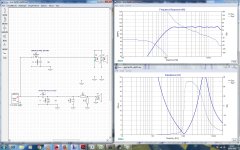
After some hours I got the attached schematic. I have almost all components for those values.
Please, let me know if it seems like a reasonable xover circuit for those drivers.
It is reasonable. The impedance at 10Hz and lower doesn't count, your speakers can't reproduce anything there anyway and the minimum in the reproduction range is at 3,5 Ohm. That's completely normal (15% under the rated impedance, which would be 3,4 Ohm) for a 4 Ohm speaker. A stable amp is recommended though.
Using the drivers in serial can be very critical because of the power distribution at tolerances and has to be avoided if possible.I think there are only drawbacks using the woofers in series.
Lower spl and I dont have a big amp to move them this way.
Also, in series, the crossover components will be bigger and the system will be more sensitive to component tolerances.
As Icg says, running them un parallel would make almost 4ohm impedance. A bit hot for my amp anyway... Will have to put a bigger heatsink.
Refarding the xover. I dont know if its a good idea to drop the highs. My room will make a boost un the bass, thats why I think it would be worst.
I'll play a bit more with the simulation and come back.
Thanks a lot for your help.
I use a midrange that is 98dB sensitive, and when the top end is eighth spaced it well keeps up with the tweeter so I can't pad the tweeter. I used to use a 96dB woofer half spaced and I had to pad the tweeter a lot, so I think sensitivity is one way you could make your amp's job easier.
Allen, the woofers are 93db/1w. So running dual I think I will get around 96-98db.
The DE500 are 107db so I think i'll have to pad them, but not sure yet how much.
As long as you are happy designing your hipass for an 8 ohm impedance > you could always use a variable Lpad to dial in the preferred horn level.
The schematic ( that you posted above ) forces a 15.5 ohm "working impedance" onto the horn circuit ( which is fine ).
This higher working impedance ( 15R > horn only ) rewards you ( compared to an 8 ohm circuit ) by allowing the use of smaller capacitors ( for the same Fc ) but punishes you by making you buy larger coils ( to arrive at the same Fc ).
- Choose your poison here ( I mostly prefer to save cost in the area of coils/inductors though many times I like to work with 10R to 12R horn circuits ).
Hi Drummer,
( For you & others to play with ), here are 4 different ( zipped ) XSim files sporting 2 different padding philosophies.
Lots can be learned from poking around in other peoples design files ( IMO ).
Each file has the possibility of being a 4-pole HP filter > ( included is a single LCR notch filter ) plus another LCR that acts as the primary element within the HF compensation scheme.
I'd suggest ( right-clicking ) on the various parts ( toggling through to "open"//"shorted"//"value" ) to see each elements effect on the overall frequency response ( and circuit impedance ).
Should you decide to use a Constant Coverage style horn, you'll need to learn about HF compensation ( for most driver/horn combos ) .
Attachments
I wanted to explain a method I mentioned earlier but I got a bit busy. Altec may be the first company to use this sort of pad.

I am assuming 10 DB padding and 1400 HZ, 8 ohm high pass for this example.
Two disadvantages of the L pad are:
lower dampening factor when adding series resistance. Compression drivers do not sound the same when you have too much series resistance. Attacks seem to be a bit blunt.
Additional power dissipated inside the cabinet or at least in the crossover.
For the choke, I use powdered ferrite torroid cores usually stolen from computer power supplies. You want a permiability of about 2-5 for the core. They are fairly easy to hand wind.
Without a pad, the values for L are 1.29 millihenry and C 10 microfarad.
10 DB power loss is .316 voltage.
I wind the torroid for 1.29 millihenry first. In this case after the center tap I would use smaller wire with 3.16 times the turns needed for 1.29 millihenry.
10db power loss results in 10X impedance so the top of the choke would appear as 80 ohms.
I get to reduce the capacitor by a factor of 10. This is helpful with lower frequency crossovers.
Now back to the original problem of impedance compensation.
I can add some series resistance to the driver.
If I add 8 ohms, I want .645 millihenry initially and 2 microfarads.
Advantages:
Less power possibly consumed in the crossover if we do not need to much series resistance.
Lower dampening factor for the driver.
Higher load impedance which will mean lower distortion for most amplifiers. This could be a problem with amplifiers with low dampening factor. May have to adjust padding.
Smaller capacitor. Useful when crossing lower.
Earl, thanks a lot for the files. Its very useful to see the behaviour of each filter. I like it.
I tried other xover designs for my drivers and I get flat freq responses using different xover points for the driver (around 1kHz) and for the tweeter (around 1,6kHz).
I wonder if its a common practice or if I should avoid using different xover points.
Daqvin, thanks for the explanation.
I would like to try this padding method, but Im not confident enough to wind it by myself.
Are there any transformer I could buy for the task with the needed values?
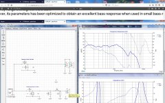
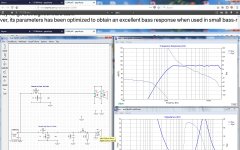
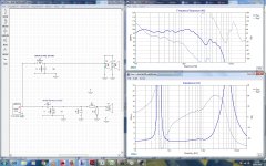
well, another afternoon playing with xsim (is more fun than PS4)
Got the right manufacturer response graph for the woofers. The one I used before were imported from Vituixcad, and was smooth, so it was easy to get a flat response.
With the right manufacturers file, things got worse, since it has a response peak at around 3,8kHz.
Earl, I played with the xovers you sent me, but could not get good graphs, so I went back to simpler, noob ones.
I got a flat graph when combined, but the impedance curve for the comp driver is not flat. If I remove C5 I get a flat impedance but I have to increase series resistor to pad highs.
Also, with the new zma and frd files, I have to put a huge capacitor for the driver xover. I can put smaller ones in parallel, but Im not sure what is less harmful for sound.
Now Im stuck and need your advice.
Guys, could you take a look at the graphs?
Thanks for your help
Attachments
sorry, the screenshots were not complete.
Don't let any of your impedance's dip below 4 ohms ( unless you have amps that are stable into 2 ohms ).
The following is particularly disturbing.
Probably more than 10dB. Are you measuring?The DE500 are 107db so I think i'll have to pad them, but not sure yet how much.
A series capacitor can do much to help and not much to hurt. IMO, don't be afraid and fix your crossover so you understand where to take the response, then you can change your parts/method to anything you want.Maybe Im wrong but a series capacitor will hurt.
You haven't decided if flat response is good or not. What horn will you use and will you listen off axis?I get flat freq responses
You should match your directivity to the woofer and this will set your crossover point. Also, it is not bad to have a lower crossover.I wonder if its a common practice or if I should avoid using different xover points.
Last edited:
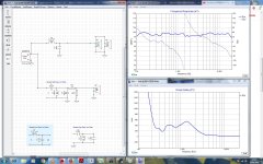
Hi again,
Earl, at the last impedance graph, I forgot to remove ground from the lp filter thats why it dropped below 2 ohms. After removed, it shows a dropping impedance from xover point that ends at around 2ohms at 20kHz.
Allen, I have not measured since I have not built the box yet, so I don´t know if a flat response will work or if it will make it sound too bright... don´t know.
Anyway, I´ll take your advice, and buy several resistor and cap values to fine tune it and then, choose the less harmful method to pad the cd.
The cd horn will be made in a CNC lathe, but not decided which curve and tune for it. I have to study it.
I know its not a very technical method, but I could make different ones and choose the best sounding. (mdf is cheap, and lathing is fun)
The problem is that 8" drivers have not too much depth and I have to make a short horn to keep time alignment.
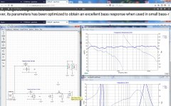
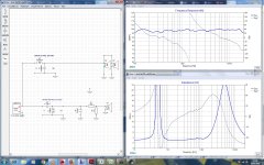
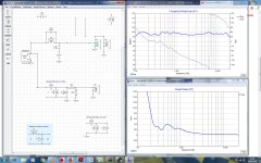
...and, back to the xover, been playing some more with xsim.
This time I tried to keep group delay as low as possible and realised that inverting cd polarity improved it.
Attached graphs. Let me know what xover schematic should work better.
Thanks again for your help
Earl, at the last impedance graph, I forgot to remove ground from the lp filter thats why it dropped below 2 ohms. After removed, it shows a dropping impedance from xover point that ends at around 2ohms at 20kHz.
Allen, I have not measured since I have not built the box yet, so I don´t know if a flat response will work or if it will make it sound too bright... don´t know.
Anyway, I´ll take your advice, and buy several resistor and cap values to fine tune it and then, choose the less harmful method to pad the cd.
The cd horn will be made in a CNC lathe, but not decided which curve and tune for it. I have to study it.
I know its not a very technical method, but I could make different ones and choose the best sounding. (mdf is cheap, and lathing is fun)
The problem is that 8" drivers have not too much depth and I have to make a short horn to keep time alignment.
...and, back to the xover, been playing some more with xsim.
This time I tried to keep group delay as low as possible and realised that inverting cd polarity improved it.
Attached graphs. Let me know what xover schematic should work better.
Thanks again for your help
Attachments
- Status
- This old topic is closed. If you want to reopen this topic, contact a moderator using the "Report Post" button.
- Home
- Loudspeakers
- Multi-Way
- comp driver zobel help!