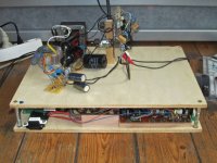
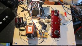
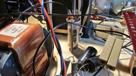
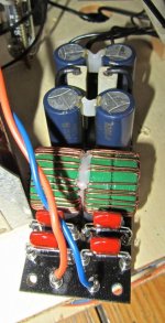
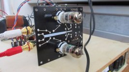
Here is my take on a tube and transformer based I/V converter..
Here: http://www.diyaudio.com/forums/tube...r-i-v-converter-differential-current-dac.html
Works quite well.
Hi Kevin, I am curious what the output impedance is using the plate choke did you do comparative measurements between choke/resistor loading?
Hi Arno,
Actually using resistive loading on the output was not a design goal and was not evaluated in this design. (I done many resistively loaded amplifier stages in the past)
The actual source impedance of the design is determined almost entirely by the rp of the triode used. It is true that the source impedance with a resistor would have been slightly lower, (no additional load current available practically speaking so this is meaningless) but this would have come at the expense of considerably higher plate voltage in order to maintain the chosen operating point.
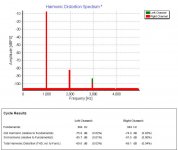
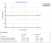
The source impedance would typically be < 2K with the 5842.
Because of the high plate currents and low rp the 5842 and other similar high transconductance triodes are well suited for choke loading and less so for conventional resistive loading.
The AC load resistance is 100K so using choke loading allows me to get a gain of virtually mu which was a design goal. Gain would have been substantially lower with a resistive load.
Actually using resistive loading on the output was not a design goal and was not evaluated in this design. (I done many resistively loaded amplifier stages in the past)
The actual source impedance of the design is determined almost entirely by the rp of the triode used. It is true that the source impedance with a resistor would have been slightly lower, (no additional load current available practically speaking so this is meaningless) but this would have come at the expense of considerably higher plate voltage in order to maintain the chosen operating point.
The source impedance would typically be < 2K with the 5842.
Because of the high plate currents and low rp the 5842 and other similar high transconductance triodes are well suited for choke loading and less so for conventional resistive loading.
The AC load resistance is 100K so using choke loading allows me to get a gain of virtually mu which was a design goal. Gain would have been substantially lower with a resistive load.
That's what I expected. Previous days I have been building several concepts, measuring and above all listening....SRPP, two stage triode and a single triode stage (2 e88cc sections in parallel)..
The latter, with plate output couple of k impedance could not drive my passive (transformer based) preamp.
Back to cathode output <100 Ohm and everything is in place...except for the gain (and I don't want an extra triode)...
So....a bit extra on the Rload DAC (move from 15 to 33 Ohms, see my other post as well) and use the extra sensitivity of the 300B SET input that is attenuaten now...
By the way...if you're already using a choke....why not go out with an output transformer???
")
<snip>
By the way...if you're already using a choke....why not go out with an output transformer???
Mostly because there is already a transformer at the input side of this design, and because there are other transformer coupled stages in the path.
Also I'm not sure that a 1:1 SE transformer at the required current and with the desired primary inductance would be economically feasible. The choke made sense to me in this location, gives me mu for gain into the required load and has reasonable DCR all at a reasonable cost.
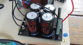
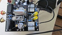
The latest setup looks pretty cool.. Progress..

- Status
- This old topic is closed. If you want to reopen this topic, contact a moderator using the "Report Post" button.
- Home
- Amplifiers
- Tubes / Valves
- Common Cathode as DAC output