Yes, you have obviously serious oscillation, heating up the zobel.
My recommendation (maybe not helpful now) would be replacing the Toshibas with MJL21194 (or MJL21196).
Amplifiers not designed for the SC5200 often oscillate with these.
Do you have a scope to determine the frequency of the oscillation?
Possible fixes would be adding base stoppers (1-10ohms) to the output devices, and/or adding a miller cap to B-C of the lower "driver" of the DoZ. (maybe 47pf)
It's normal that the bias control acts a bit erratically with an oscillating amp.
An "unearthed" heatsink often cause oscillation with fast output devices, possibly connecting it to ground solves the problem.
Can you show a photo of your Toshibas? Most fakes can be identified by their casing.
Mike
Thanks for your reply ")
I checked the output on the scope. It is around 14.3Khz oscillation at full amplitude. Other interesting points are that the oscillation starts as soon as the bias "cascades". Idling at around 0.03A, that small movement of the dial suddenly ups the bias to over an amp and the oscillation starts; it may even be the other way round with the oscillation triggering the sudden bias increase?
Tried earthing the sink, it had little effect, perhaps changing the frequency of oscillation marginally
It may come to changing these output devices, pity the MJL21194 is so expensive. Apparently the 2N3773 also works and is cheaper, but is also TO3 which makes mounting more difficult; by the time I have aluminium angle it may cost the same.
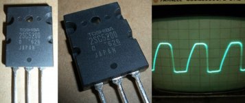
I attach pictures of an output device and the scope trace (set at 20uS, 10V)
I checked the output on the scope. It is around 14.3Khz oscillation at full amplitude. Other interesting points are that the oscillation starts as soon as the bias "cascades". Idling at around 0.03A, that small movement of the dial suddenly ups the bias to over an amp and the oscillation starts; it may even be the other way round with the oscillation triggering the sudden bias increase?
Tried earthing the sink, it had little effect, perhaps changing the frequency of oscillation marginally
It may come to changing these output devices, pity the MJL21194 is so expensive. Apparently the 2N3773 also works and is cheaper, but is also TO3 which makes mounting more difficult; by the time I have aluminium angle it may cost the same.
I attach pictures of an output device and the scope trace (set at 20uS, 10V)
Attachments
Yes, it is very likely that the starting oscillation triggers the bias up.
From the photo, the Toshiba at least look like genuine, no obvious fake.
~14khz is way too low frequency to expect from an oscillating amp, check all soldering, all devices for correct polarity, resistors/caps to have correct value. There is something very wrong...
Mike
From the photo, the Toshiba at least look like genuine, no obvious fake.
~14khz is way too low frequency to expect from an oscillating amp, check all soldering, all devices for correct polarity, resistors/caps to have correct value. There is something very wrong...
Mike
MikeB said:From the photo, the Toshiba at least look like genuine, no obvious fake.
At a second look, comparing with other devices, you see that the printing on yours uses the wrong font...
Sorry, they are very likely to be fakes. Does someone have an up to date picture of ROHS-Toshibas?
Mike
Hi,
my Toshibas are not printed. I think they have used a laser to leave a very feint trace that is difficult to read until the light is at just the right angle.
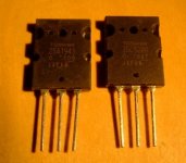
The 4 indents in the sides are for clamping the backplate into the moulding machine. The clamps always leave part of the backplate showing where the plastic is prevented from flowing under the clamps.
edit
Pink's left most device shows the bare backplate where the clamps were during moulding.
my Toshibas are not printed. I think they have used a laser to leave a very feint trace that is difficult to read until the light is at just the right angle.
The 4 indents in the sides are for clamping the backplate into the moulding machine. The clamps always leave part of the backplate showing where the plastic is prevented from flowing under the clamps.
edit
Pink's left most device shows the bare backplate where the clamps were during moulding.
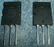
Thanks for the responses. Now I know what to look for I understand what you mean. Interestingly I compared them to my 2SA1943s from the same supplier and the metal shows much clearer. I show a photo of this comparison.
The 2SC5200s do also have a marking in this area, it looked like a very thin layer of plastic and so I scratched it off with a knife and it revealed shiny metal underneath. Would a fake still do this?
The writing shows up much clearer under the flash (at angles at least). In normal light it is only readable in certain positions (pretty much anywhere so long as light is not reflecting straight off of it). hfE is around 60 on most devices, oddly around 80 on 1 of the 6.
The big question is would fakes create this erretic behaviour? I have checked this circuit so much that I can't see there being any possible problems. It's not a complicated circuit in the first place, I built the P101 succesfully first time; even Moog 24db filters I've layed out on stripboard and had working with much less hassle!
Attachments
I had a similar issue with fakes of those toshibas... Bias would go from ******* crazy to switching off the transistor by jsut slightly touching the bias trimpot... was like a giant seesaw... and had me nearly in tears... took long to grab some pliers and break one open... and it was the fakest of fake...
Did your amp oscillate at low frequuency too? I suppose it depends on the application as to exactly how fakes will behave, but the highly sensitive bias is very much what I'm experiencing.
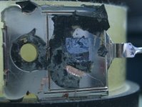
I had to try and settle this so I cracked one open. Unfortunately I don't have a Dremel or anything so a hammer and chisel were all I could use. It's in quite a state but you can kind of see the silicon die still.
I still cannot see any errors in the circuit itself and I have checked it many times and have tested every component.
Attachments
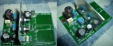
Hmm, I'm using the Rev-B board from Rod. It's so simple and neat that I just can't see any possibilty for problems. The only thing is I have left the input "open", not shorted or with a source connected, but that shouldn't be a problem? I've tested every part, even capacitors, and checked every solder joint (by measuring continuity further down the track). I've removed any flux which could cause a problem. Here is a photo of the PCB.
Attachments
Dr.EM said:Thanks for your reply
I checked the output on the scope. It is around 14.3Khz oscillation at full amplitude. Other interesting points are that the oscillation starts as soon as the bias "cascades". Idling at around 0.03A, that small movement of the dial suddenly ups the bias to over an amp and the oscillation starts; it may even be the other way round with the oscillation triggering the sudden bias increase?
Tried earthing the sink, it had little effect, perhaps changing the frequency of oscillation marginally
It may come to changing these output devices, pity the MJL21194 is so expensive. Apparently the 2N3773 also works and is cheaper, but is also TO3 which makes mounting more difficult; by the time I have aluminium angle it may cost the same.
I attach pictures of an output device and the scope trace (set at 20uS, 10V)
Are you sure about those 14kHz oscillation? Its very low. This would be a major change in circuit parameters, not just an ungrounded heatsink. I don't know this particular circuit but my best guess would be to closely check all component values. Possibly you have mixed up components or component values. Look at all capacitor values, except the ones in the power supply. If there are any compensation caps, and you mistakenly put in 100nF instead of 100pF for instance, you can get these things. But again, make sure it is indeed a low 14kHz, if not disregard the above
PS Are the driver and output transistors properly isolated?
Jan Didden
I think a photo of how the boards are placed realitive to the heatsink may also be usefull... I had some issues too, where the board was fastened over the heatsink but with only enough clearance to avoid shorts... I guess it was a capacitive effect... lifting the same boards to about 1cm from the sinks cured the affliction...
Also, try dropping Rod a mail, he is a very nice guy and normally replies quite fast, even to non-customers...
Also, try dropping Rod a mail, he is a very nice guy and normally replies quite fast, even to non-customers...
Thanks for the replies again
I have checked everything 100% which is why it is so baffling. Meaured every resistor, checked polarity of transistors, traced the PCB back to the schematic even.
The period of the oscillation frequency is 70uS which I believe equates to 14Khz? I've tried the miller cap too to no avail (33pF mounted under board).
The boards soldered joints have a clearance of under 1cm from the heatsink due to the thickness of the output packages, but the board is designed with this mounting scheme so I can't imagine it causing any trouble? None of the joints are spiky or stick far up from the board.
There is isolation on the drivers, its not very clear because it's just clear mica washers, I tested there were no shorts with ohmeter.
I may have to email Rod directly as you suggest, I really am stumped by this. Incidently, I built one of my P101's this afternoon (using the PCB) and it appears to work flawlessly right away (no high power test yet). It's a more complicated amp too!
Hi,
it could be overheating of the drivers that is causing this set up problem.
The mica washers provide electrical isolation but they introduce two insulating air gaps that increase the thermal resistance dramatically.
Both faces of the mica washer must have a thermal jointing compound to completely eliminate any air from the joint. The compound should be spread fairly thinly and when bolted up there should be some metal to mica contact with thermal compound taking up the tiny gaps where the surfaces are scratched or slightly uneven.
ya, I have this problems some days when I was implementing my symasym version: quiescent current increased madly up to 0.5A when I set the bias current to 70ma, then one of my 2sc5200 passed away. I can be sure that this oscillation is of very high frequency, I can tell that because I was listening to my FM radio at the time when I turn on the fault amp and the radio send out noise. further more my 10 ohm resistor in zobel network got burning hot. This oscillation especially occurred when I was upgrading the amp with better gain device.
I have found that oscillation come from false grounding and I have placed the pre drive rail cap at the wrong place.
I have either done this and the oscillation went away: Put the rectifier caps (15000mf/63v) on the output board and take their ground as common ground to the predrive. Place the power filter caps at the entry points in to the pre drive.
Now my amp is no longer oscillate and quiescent stay stable at the value I set.
- Status
- This old topic is closed. If you want to reopen this topic, contact a moderator using the "Report Post" button.
- Home
- Amplifiers
- Solid State
- Commercial or DIY amps