Thanks udaily, if you are so in the know, you could have just answered my question. But instead you chose to try and patronize me. That gives me the impression you are not a very pleasant person, prove me wrong. Please be assured that, I did "read" his comment very well, I Googled "rf filter calculator" and several other combinations and did not find what I was looking for, hence I asked the question. Don't believe me if that's your disposition, but don’t blame me for it.
Guitar Pedals: R-C Filter Calculator
rc_simple_filter [Electron Coaxing Techniques & Notes]
First two on google with search term 'input roll off calculator' - you tried once and gave up?
udaily was not being condescending at all, that is not his way. He gave you the info you needed to help yourself. It's a better method of learning and teaching.
Nop, you are both wrong, I did try and look for an answer for about 20min, read a few pages and a wiki, found a couple of formula’s that I couldn't figure out the variables for etc.., but no calculator template.
I still don't see how I could have deducted from Andrew reply that 'input roll off calculator' was the search term to use. But hey I only have an MSc degree with honors from UCL & worked in ICT and telecommunication for 20 odd years, what would I know about finding information online.
Thanks anyway for answering my question. I hope I can return the favour sometime soon. It's easy when you know what to look for, isn't it? ;-)
On what ground did you assume I didn’t make any effort in the first place, to find an answer? And yes, since the answer to that question is “none” (ie you had no ground), imo you are both pretty condescending in your replies. If not, what would you consider “condescending” to mean? You have no idea whom you are addressing, right? Think about it.
Last edited:
Note there is a typing error: It should say "The series resistor and the following shunting capacitor to Signal Ground form a low pass filter.................The F-3dB (= 1 / 2 Pi R C) is usually set..................
RF filtering.
The series resistor and the following shunting resistor to Signal Ground form a low pass filter that attenuates the high frequencies............Listen and decide what suits you.
Start with F-3dB @~50kHz and see if that is audible. You may have to go as high as 300kHz to make this RF filter inaudible for you and your system.
.............Is there an online calculator or formula in which I can plug in the two resistor values to determen the RF cut-off frequency?
............ you could have just answered my question. ..............
Just read my reply.Nop, you are both wrong, I did try and look for an answer..........................On what ground did you assume I didn’t make any effort in the first place, to find an answer?..............
I gave the standard "online calculator" for a single pole filter.
I gave you a start and end value for the filter F-3dB frequency.
I gave the the physical layout of the TWO components required to create that RF attenuating filter.
Just read the reply, instead of complaining.
Last edited:
Andrew, Sorry if it appeared to you as if I was complaining about your post, that was never my intention and I’m very appreciative of you input and that of others in order to be able to build my first GC.
I merely responded to Udaily’s reply suggesting I hadn’t read your post and then responded to Passive420 for suggesting “I gave up”. Neither of which was the case.
I’m very surprised to be receive all these accusations in this thread, by merely posting a question, bizarre..
I merely responded to Udaily’s reply suggesting I hadn’t read your post and then responded to Passive420 for suggesting “I gave up”. Neither of which was the case.
I’m very surprised to be receive all these accusations in this thread, by merely posting a question, bizarre..
This my first post so please forgive me if this is wrong place to ask this question.
I recently put together one of the LM4780 boards from Audiosector (to use in stereo for testing before finishing the whole kit).
I have tried three different potentiometers but there seems to be very little attenuation and certainly not all the way down to cut off.
The first two, a 10k and 20k (with a "B" designation I assume for "Linear") the attenuation is faint at best and not down to silence.
The third pot, is one retrieved from my old Technics amp with the makings of 100k Ohm B. This one does noticeably attenuate but not to cut off. To help make it clear what I am saying, the volume goes from loud to less loud.
Power is from 18v +- rails and rectifiers to 26.5v and 25v.
Thank you for any assistance on this question.
Phil
Hi Phil,
Pin 1 should go to signal ground on PCB and RCA jacks then pin 2 (wiper) to amplifier and pin 3 to preamp output.
See image below under volume control
An externally hosted image should be here but it was not working when we last tested it.
Ciao!
Do
hi guys haven't been on in a while but i have a question that i need help me with.
i would like to add a auto on/off circuit to the amp and need some way of implementing it.
i plan on using the amp for tv sound and would like to have it turn on and off with the tv. it will be using rca inputs.
i would like to add a auto on/off circuit to the amp and need some way of implementing it.
i plan on using the amp for tv sound and would like to have it turn on and off with the tv. it will be using rca inputs.
Dear Peter D.,
I have received your LM4780 kit, it looks great.
In the first place I planned to build the kit in parallel configuration but because I have speakers that can be bi-amped (Mission M52) I'm considering to build the kit 2 x stereo.
My question is what you think will sound better.
I guess that in parallel mode the overall power output will be higher but if the sound quality in double stereo mode will be much better its something I can live with.
Also I probably can use a smaller toroid for powering the tweeters I guess.
Any info would be very welcome.
Greetz,
Joery
After fixing my Denon DCD-1500II CD player I am looking at building an amp to get the sound to come out ")
Will be buying one of Peter's LM3875 kits, probably the standard initially in dual mono mode.
I have been looking at toroids for it and have these as an option : Buy Toroidal Transformers 2 Output Toroidal Transformer, 225VA, 25, 50V Nuvotem Talema 0225P1-2-025K online from RS for next day delivery. At 25v/25V 225VA are they a good choice?
Also want to put a volume pot in it and was looking at one of these: Valab 23 Step Attenuator Potentiometer 10K Stereo LOG | eBay
or one of these: Valab 23 Step Ladder Type Attenuator Potentiometer 50K LOG Stereo | eBay
Any advice would be appreciated.
Cheers
Bruce
I don't see a problem with the transformers. I am surprised Peter hasn't seen your post yet, he is usually on the ball.
Thanks for the reply about the transformer, I will use it to supply both amplifier boards.
I have searched a lot about sound quality difference between parallel and stereo configuration of the LM4780 but did not find good info about it.
I hope anybody can give me some advice.
Thanks in advance,
Joery
I should add that a dual secondary 25Vac transformer will end up around 71V after adding up both DC rails... theoretically. However a lightly loaded transformer will put out higher voltage than you expect and this fact coupled with a higher than rated primary voltage could net you an unsafe secondary voltage. With chipamps you want to know the voltage from your wall and you want to make sure you dont come close to the max allowed by the chip.
For instance the toroid you showed is for 25Vac secondaries but under no load it gives 27.42Vac on a 230Vac line. What if you are getting 240Vac that day? Then you end up with ((240/230)*27.42)*1.414 which is 40.457VDC. Mulitply that by two rails and you are at 80.9VDC which is getting close to the max you can use on a chip amp. I dont know how much the voltage from your wall fluctuates so this is something to think about. I use 18-22Vac secondaries with chip amps.
Getting max voltage from your toroid does not correlate with getting the max out of your chip amp in any way but watts. Since you dont need big watts, most likely, you might consider the 18V toroid. 18V sounds great with my amps. Another thing to consider is the price of a stiff power supply of higher voltage. With the 18V secondaries you can get away with 35V rated caps instead of having to jump to the 50V rated caps which will cost more and be larger in size.
Uriah
Last edited:
Dear Udailey,
Thank you for the information.
In Holland where I live the voltage is quiet stable and I have 50V caps So I guess its not going to give problems.
I sometimes like to play my music loud so that's why I chose the 25V transformer.
But as I stated in my previous comment I will choose quality over power.
If a setup that produces less power will give more quality I will choose that.
Last edited:
Build LM4780 parallel amp
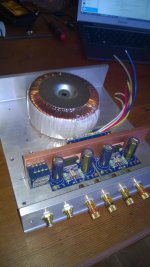
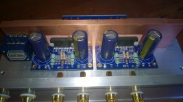
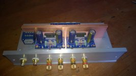
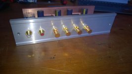
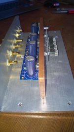
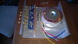
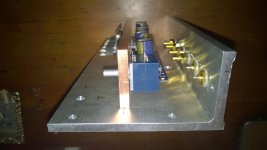
Here the progress of the build of my LM4780 parallel amp.
The pictures shown are of the amp upside down, the sides I want to cover with oak wood and the bottom will stay open.
The transformer is 2 x 25V 10A 500VA
The heat-sink inside is a copper bar 8 x 50 x 200mm
The cover is aluminum 7mm thick
The star ground I've planned in the middle of the copper bar
The insulation between the LM4780 and the heat-sink is made with silica pads without paste.
I've used an Alps pot for volume control.
Any comments and/or suggestions are very welcome
Greetz,
Joery
Attachments
- Home
- More Vendors...
- Audio Sector
- Commercial Gainclone kit- building instructions