zebra100 said:Hi Peter,
I connected 4 wires between each of the rectifier and amplifier boards (V-,PG-,PG+,V+) and then the L+R CHG connections to the chassis earth point with a 10ohm resistor on each. I wanted to try and keep both channels seperate, but this is causing a low hum. I have tried it with and without the resistors, and I get more hum without them. I am also getting some distortion in the low frequency range.
Is there any reason why I can't use the same set up as you have used (page 4 of this thread), connecting both channels together with 14ga solid copper wire, or will it have to be modified in some way?
Regards,
Chris.
Well, it just goes to show that if you get the grounding right, this kit can sound awesome.
I used Peter's example on page 4 as a guide, and it works a treat. The only difference is that I used thick (@twice the diameter of the holes on the PCB) silver plated copper wire as the star power earth point between each channel. I had to do a lot of fettling (filing down)of the ends to get the wire to fit in the PCB. It was also very difficult to solder the wires on to the earth point. I had to rough it up slightly and use silver solder to get the wires to stick.
")
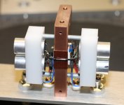
While the projects described so far were using printed boards, I would like to present now an elegant way to build an amp circuit without PCBs, using point to point wiring technique.
It so happens that I recently received an order for LM1875 amp, which I never tried before, so there was not other way as going p2p.
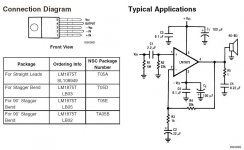
The amp circuit as presented in National's datasheet:
It so happens that I recently received an order for LM1875 amp, which I never tried before, so there was not other way as going p2p.
The amp circuit as presented in National's datasheet:
Attachments
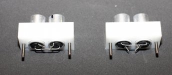
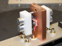
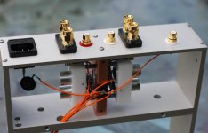
I'm using my standard chassis and start with mounting the chip to copper heatsink. The chip case is not insulated, so isolation pad is required as well plastic washers under the mounting screw (an aluminum oxide pad was used here).
I also install 3 famous resistors: 22K for input shunt and feedback and 1.5K gain setting Riken. The customer asked for lower gain that's why I didn't use 680R as usually.
You can also see input wires coming from RCA socket (23awg silver wire from DH Labs) and speaker output wire (19awg Kimber TCSS)
Attachments
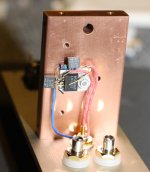
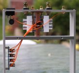
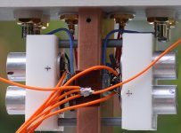
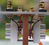
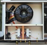
The power wires from rectifier board are directly connected to cap pins (2 for V+ and 2 for V-), the ground wires from rectifier board connect to common star ground point at the center of previously mentioned (black) wire.
From here, the common ground point is connected through thermistor (CL-60) to Earth ground pin on power entry module (chassis is not grounded yet, awaiting installation of bottom panel), the additional RCA is used to connect external devices to amp's star ground (customer's special request)
From here, the common ground point is connected through thermistor (CL-60) to Earth ground pin on power entry module (chassis is not grounded yet, awaiting installation of bottom panel), the additional RCA is used to connect external devices to amp's star ground (customer's special request)
Attachments
Attachments
Peter Daniel said:From here, the common ground point is connected through thermistor (CL-60) to Earth ground pin on power entry module (chassis is not grounded yet, awaiting installation of bottom panel), the additional RCA is used to connect external devices to amp's star ground (customer's special request) [/B]
Hi Peter
Could you please tell me more about this thermistor and how you connect it? I experience a rather loud "thump" in my speaker when I shut off other components before I shut off the amp. I suppose this thermistor is ment to help on this problem?
Best wishes
Jan Ove
Could you please tell me more about this thermistor and how you connect it? I experience a rather loud "thump" in my speaker when I shut off other components before I shut off the amp. I suppose this thermistor is ment to help on this problem?
Always turn your amps off FIRST!
Nuuk said:
Always turn your amps off FIRST!
Yes, of course. But sometimes I want to listen to my turntable after a session with the CD player. It is rather inconvenient to shut of the amp, turn the switch and the turn the amp on again. I'm rather lazy, you see
best wishes
Jan Ove

- Home
- More Vendors...
- Audio Sector
- Commercial Gainclone kit- building instructions