Problem solved maybe
My amp still overheats and isn't right but I think I figured out the problem. I looked back at the instructions and I believe I have input and output wires wrong.
I have a picture and the black and white wires are input output; you can see the connection to the terminals for the output. I think I should move them to the Cz Rz locations
(I hope the picture link works it's my first try)
It l
An externally hosted image should be here but it was not working when we last tested it.
Don't move anything to Cz, Rz, those pads are not being used.
It should be obvious that IN means input and OUT stands for output")
One other thing; the nuts on mounting screws are two big, while power plains are protected by solder mask, it is not enough isolation and you are risking shorting the rails to the chassis: use either plastic isolation washers or screws with small heads.
It should be obvious that IN means input and OUT stands for output
One other thing; the nuts on mounting screws are two big, while power plains are protected by solder mask, it is not enough isolation and you are risking shorting the rails to the chassis: use either plastic isolation washers or screws with small heads.
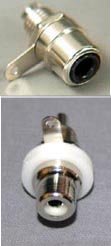
Grounding RCA Jacks
I saw this earlier and noticed that my RCA input jacks clearly aren't isolated from the chassis. Actually I have them screwing fairly tightly into the chassis and there is no isolation washer. Could this be my
Are there isolated and unisolated RCA Jacks?
Tom
The RCAs need to be isolated from a chassis. You are using what looks like Cardas RCAs, they should come with plastic isolation washers.
I saw this earlier and noticed that my RCA input jacks clearly aren't isolated from the chassis. Actually I have them screwing fairly tightly into the chassis and there is no isolation washer. Could this be my
Are there isolated and unisolated RCA Jacks?
Tom
Re: Grounding RCA Jacks
Tom-
The isolated type come with plastic washers and require a larger hole.
Alternatively you can mount the non-isolated style on a plastic/phenolic plate, so they are electrically isolated from the rest of the chassis.
Cheers
John
tbrooke said:
Are there isolated and unisolated RCA Jacks?
Tom-
The isolated type come with plastic washers and require a larger hole.
Alternatively you can mount the non-isolated style on a plastic/phenolic plate, so they are electrically isolated from the rest of the chassis.
Cheers
John
Attachments
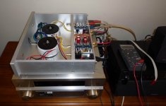
More Troubleshooting (newby)
I can't figure out what to do next
So far I have
1. measured voltages at V+ PG+ V- PG- etc its about 35 volts
2. Checked DC Offset on output terminals - it varies between
.005 V .050V I have tried it with a 8 ohm load and I used a preamp to vary the input and I have even played music which does come out but unamplified and distorted.
3. Removed the bolts that held amp boards down and may have caused a short
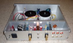
see picture:
http://picasaweb.google.com/tom.brooke/Amp?authkey=Gv1sRgCPaAyKmCqN6wdQ#5331279046144343858
4. Insulated RCA input jacks.
Amp still get very hot, no sound except for static
I ran continuity checks with my multimeter and it seems almost everything may be shorted to ground but then again maybe this is the way it is supposed to be - it is ground - maybe continuity isn't the way to check for shorts
So
1. Anything else to check and how?
Visually soldering looks ok
2. Could I have damaged the LM3875? How do I check?
3. Anyone in NC that can check it?
4. Should I order a new kit and start from scratch?
Tom
I can't figure out what to do next
So far I have
1. measured voltages at V+ PG+ V- PG- etc its about 35 volts
2. Checked DC Offset on output terminals - it varies between
.005 V .050V I have tried it with a 8 ohm load and I used a preamp to vary the input and I have even played music which does come out but unamplified and distorted.
3. Removed the bolts that held amp boards down and may have caused a short
see picture:
http://picasaweb.google.com/tom.brooke/Amp?authkey=Gv1sRgCPaAyKmCqN6wdQ#5331279046144343858
4. Insulated RCA input jacks.
Amp still get very hot, no sound except for static
I ran continuity checks with my multimeter and it seems almost everything may be shorted to ground but then again maybe this is the way it is supposed to be - it is ground - maybe continuity isn't the way to check for shorts
So
1. Anything else to check and how?
Visually soldering looks ok
2. Could I have damaged the LM3875? How do I check?
3. Anyone in NC that can check it?
4. Should I order a new kit and start from scratch?
Tom
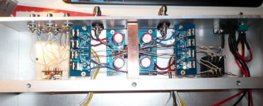
One other thing to check is if you place resistors in right places. I recall someone had sililar problems and it was because of mixed up resistors. You can find some pics here: http://www.diyaudio.com/forums/showthread.php?postid=1508848#post1508848
R1 which is 220R looks slightly different now, but the other two 22K should be the same.
If the chip shows offset, that may indicate it's not damaged.
If you won't be able to make it work, you can ship it back to me and I will fix it
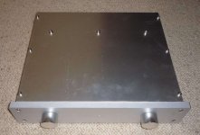
Congratulations, it looks really good
R1 which is 220R looks slightly different now, but the other two 22K should be the same.
If the chip shows offset, that may indicate it's not damaged.
If you won't be able to make it work, you can ship it back to me and I will fix it
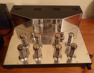
cyxg said:I finished my 3875 chip amp, sound very good!
Congratulations, it looks really good
I've been directed to this thread and I'm looking forward to ordering all my parts and starting the build.
All the prices look reasonable and then I came to the transformer, which was a nice kick in the guts.
So I searched around for options in Australia and can only find 2x18V 300VA Toroidal Transformers and 2x25V 300VA Toroidal Transformers.
My plan is to use this amp with 6ohm speakers, which transformer should I go for?
Also what is the difference between this transformer and http://www.airlinktransformers.com/transformer/0300222-open-style-with-leads.asp]this one[/URL].
I ask because in one build I've seen (with the airlink t'former) there was two used and in another build only one partsexpress piece was used.
Thanks,
Matt!
Peter Daniel said:One other thing to check is if you place resistors in right places. I recall someone had sililar problems and it was because of mixed up resistors. You can find some pics here: http://www.diyaudio.com/forums/showthread.php?postid=1508848#post1508848
R1 which is 220R looks slightly different now, but the other two 22K should be the same.
If the chip shows offset, that may indicate it's not damaged.
If you won't be able to make it work, you can ship it back to me and I will fix it
Congratulations, it looks really good
I'll check - the Rf reister is the one that can be mounted on LM3875 pins Right?
- I'll do some more checking and I may contact you by email about sending it up for you to look at - but I'm going to try a few more thiung and see if I can solve it myself
Thanks
Tom
tbrooke said:I'll check - the Rf reister is the one that can be mounted on LM3875 pins Right?
Yes, that's the one; it can be mounted either directly on pins or in a spot marked Rf. It is 22k and the other 22k resistor is input shunt (R2). You can't go wrong with R3 as it' bigger (680R) but R1, which is 220R, can be mixed up with one of 22K.
Peter Daniel said:One other thing to check is if you place resistors in right places. I recall someone had sililar problems and it was because of mixed up resistors. You can find some pics here: http://www.diyaudio.com/forums/showthread.php?postid=1508848#post1508848
R1 which is 220R looks slightly different now, but the other two 22K should be the same.
If the chip shows offset, that may indicate it's not damaged.
If you won't be able to make it work, you can ship it back to me and I will fix it
Went back and checked resisters and the 220 was ok but the 22K's (sg) were 246 R and 265 R - not sure where I got them from they must have been in the kit - might check and see if Radio Shack has 22k or else digikey.
I believe that might be the problem
tbrooke said:- not sure where I got them from they must have been in the kit
That could not be in a kit as all 22k resistors are cut 4pcs at a time from a same tape. Unless you bought a used kit
Peter Daniel said:Congratulations, it looks really good
Hi,Peter
i running the amp 2 days.my speaker is PROAC response 2.5/8ohm. To compare with my another Velleman K4040 Stereo Vacuum Tube Amplifier. http://www.tubedepot.com/diy-k4040.htmlI feel lost some treble and bass not clear.
Could you tell me how to improve it.
Thanks
Attachments
mattcalf said:...So I searched around for options in Australia and can only find 2x18V 300VA Toroidal Transformers and 2x25V 300VA Toroidal Transformers.
...
Hi, could you tell me the store which i can buy this Toroidal transformer.
Thanks
Hi, could you tell me the store which i can buy this Toroidal transformer. Thanks
bay seller: eecomponent sells these transformers.
http://www.altronics.com.au/ also offers them and so does Jaycar.
cyxg, attached is a BOM I've done up for sourcing things needed for this build (aswell as a speaker build) in Australia.
Attachments
mattcalf said:
cyxg, attached is a BOM I've done up for sourcing things needed for this build (aswell as a speaker build) in Australia.
Thank you very much
- Home
- More Vendors...
- Audio Sector
- Commercial Gainclone kit- building instructions