For calculation of temperature deviation it isn't need to know static power dissipation. Only absolute dissipation deviation affect on temperature changes. If transistor work on higher voltage with the same AC current signal, temperature deviation will be higher. If use scheme that decrease voltage when current starts grow as power dissipation remains constant, the thermal distortions will not appear.

Kostya-M said:For calculation of temperature deviation it isn't need to know static power dissipation. Only absolute dissipation deviation affect on temperature changes. If transistor work on higher voltage with the same AC current signal, temperature deviation will be higher. If use scheme that decrease voltage when current starts grow as power dissipation remains constant, the thermal distortions will not appear.
To do this precisely for zero dissipation shift requires a very special load characteristic---and that loading can itself involve distortion-producing nonlinearity.
The easier thing to do is use a differential stage with local series feedback and specific resistive loading and bias points so that at quiescence the dissipation of each side is equal, and a deviation from this point by a differential voltage drive reduces the dissipation of each device equally (regardless of sign). The simplest of these circuits by themselves have fairly low gain, but using the principle in some of the circuits mentioned by forr can give you good overall performance in many ways.
Feucht gives the details in his book and online materials.
forr said:
I have no exemple of VLF distorsion in mono-transistor input stage.
whre thermal effects should be much more sensible. Worth investigation too.
An ordinary electrical negative feedback helps a lot here.
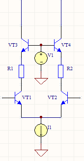
It's better to use modified cascode as on this pictureThe simplest of these circuits by themselves have fairly low gain, but using the principle in some of the circuits mentioned by forr can give you good overall performance in many ways.
Hi Kostya-M,
It would be better to clamp the negative potential of V1 to the point where the emitters are coupled.
This circuit has been proposed by Perrot, V1 provided by a few diodes, and subjectively tested.
Among about 14 circuits, it reaches the third position on the podium.
It would be better to clamp the negative potential of V1 to the point where the emitters are coupled.
This circuit has been proposed by Perrot, V1 provided by a few diodes, and subjectively tested.
Among about 14 circuits, it reaches the third position on the podium.
Note that in virtually every audio amplifier, most stages
are run in class A. Thus there is relatively little modulation
of the power dissipation with signal swing. Output stages
are one exception to this generalization.
This "little" modulation causing high degree of distortion in signal stages because of high gain.
Thermal effects can be apparent in monolithic op-amps
but careful design and layout symmetry can minimize and/or
eliminate these.
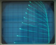
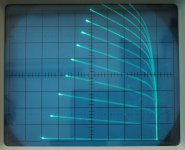
A simple solitary BJT shows thermal effects when examining in a curve tracer. See attached On-Semi BC560C and original non-fake(!) Hitachi 2SA1081 BJT photos that I've taken about a decade ago. You should see a straight line, but a loop is visible on BC560C. Same setup, same load but no loop on 2SA1081.
Thermal coupling is inherent in BJTs, FETs even in tubes. The 2SA1081 is far better here.
As Nelson said, in a well-designed amp, thermal distortion
effects should be more like third-order or lesser effects,
not primary distortion drivers.
"should be..."
Could you please send me a list of well designed amplifiers ? Or at least the principles of how to design an amplifier to be a well designed amplifier ?
") I think better to measure but not in the conventional way.
I think better to measure but not in the conventional way.Attachments
I discover this thread only today.
What it has not been stated above about Perrot is that, at the end of his famous writings in "L'Audiophile", he proved to be unable to show that a standard amplifier with NFB suffers from thermal distorsion.
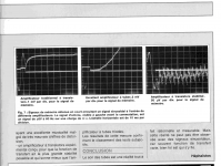
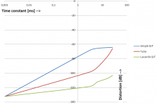
Attached Perrot's measurements results that shows that a standard amplifier with NFB suffers from thermal distorsion: Comparing a simple BJT, a tube and a low thermal BJT amplifier.
Please note: vertical sensitivities are 1mV/div, 2mV/div and 50µV/div.
Included an own made time constant vs distortion diagram to understand more easily the measurement results.
"Conclusion - The sound of the tubes is a completely rational and measurable reality. But this reality cannot be observed with sinusoidal signals, because often transfer function varies, well crazy is who relies on it." ... who relies on non interrupted constant sinusoidal signals like THD, IMD, TIM and DIM measurements. These signals are series of sinus signals and not shows the thermal distortion of amplifiers. With these signals the amplifier is in a non-changing state after a few seconds from a thermal point of view.
Attachments
I have attached the article from which I quoted above.
Krisztián, you've got a PM.
A simple solitary BJT shows thermal effects when examining in a curve tracer.
This doesn't, however, usually matter at all to the input stage differential pair where the variation in current for low frequency signals is absolutely tiny in a well designed amplifier - on the order of microamps.
This puts the differential pair in a very linear area of operation, and in particular any heating due to the microwatts of variation is also very linear. So not only are the (differential) thermal effects small, they are linear anyway.
The common-mode variation is larger, for instance if the input swing is 3V p2p and the supply +/-50V, that's 6% variation (say each transistor has 2mA, that's a variation of 6mW over the cycle.
However the common mode variation of Vbe isn't seen by the rest of the amp, assuming the transistors are the same sort (and have the same thermal properties) - only the difference in temperaure between the transistors matters. And the Vbe/temperature relation is constant, it doesn't rely on Vbe matching or hfe matching, so you don't even have to match the devices well to avoid common-mode thermal effects from being an issue.
The place you might have to worry about thermal issues is the VAS which has large power variation over the cycle. So you'd expect to see the VAS linearity drop at low frequencies due to this. However here the day is saved by the fact that the VAS is current-driven in a standard design with current-mirror load for the input pair. And you can cascode the VAS to avoid this entirely. So again thermal Vbe changes aren't really doing anything much in a well designed amp.
So overall the low frequency distortion in a well designed 3-stage amp isn't measurably affected by thermal distortion (and note any thermal distortion can have upto 100+dB of feedback to cancel it out at these frequencies).
So seeing a low frequency rise in distortion in an amp usually a sign the basic topology is lacking (or that there are some electrolytics of too small a value in the chain).
The thermal issues that I suspect really matter most with amps are to do with bias stability and the thermal feedback that's meant to stabilize the bias as the load changes and during warm-up. If this goes wrong you can get periods of complete under-bias which leads to very definite cross-over distortion (or even oscillations). And unfortunately people do get this wrong, probably quite often, as its a lot of work to characterize the thermal response of an amp under a range of varying loads - you cant measure the die temperatures directly, so you have to monitor the bias frequently between load changes over sustained periods of time.
And worse this stuff depends on the heatsink geometry, so that simply building the exact same circuit on a different heatsink could lead to poor bias management in one case and not the other... That definitely seems more of a worry than microwatt changes in dissipation in input transistors at 20Hz.
Dear Mark,
Thank you for your reply!
I first encountered the whole problem on the page of our forum member Peufeu (https://www.diyaudio.com/forums/members/peufeu.html) here: Memory Distortion Philosophies. That’s why I got to know Lavardin amps and the work of Gerard Perrot.
The problem is that, in my opinion, the thermal effect generated in the differential amplifier is not a common mode, but a differential mode, and cannot be distinguished from the musical signal we want to amplify.
You last sentence is a key information. Thank You! However because heating and cooling has the exponential time function, the current thermal error signal is not proportional to current audio signal.This doesn't, however, usually matter at all to the input stage differential pair where the variation in current for low frequency signals is absolutely tiny in a well designed amplifier - on the order of microamps.
This puts the differential pair in a very linear area of operation, and in particular any heating due to the microwatts of variation is also very linear. So not only are the (differential) thermal effects small, they are linear anyway.
The common-mode variation is larger, for instance if the input swing is 3V p2p and the supply +/-50V, that's 6% variation (say each transistor has 2mA, that's a variation of 6mW over the cycle.
However the common mode variation of Vbe isn't seen by the rest of the amp, assuming the transistors are the same sort (and have the same thermal properties) - only the difference in temperaure between the transistors matters. And the Vbe/temperature relation is constant, it doesn't rely on Vbe matching or hfe matching, so you don't even have to match the devices well to avoid common-mode thermal effects from being an issue.
These were invesigated by Peufeu here: Memory Distortion Philosophies - Part 2, The input stage
The place you might have to worry about thermal issues is the VAS which has large power variation over the cycle. So you'd expect to see the VAS linearity drop at low frequencies due to this. However here the day is saved by the fact that the VAS is current-driven in a standard design with current-mirror load for the input pair. And you can cascode the VAS to avoid this entirely. So again thermal Vbe changes aren't really doing anything much in a well designed amp.
You're right, VAS is the most vulnerable.
VAS stage investigation by Peufeu: Memory Distortion Philosophies - Part 5 : Circuits, continued
I'm still not sure whether we can characterize memory type distortions with THD or not. I think we cannot since some distortion only happens at the start of a sine wave, but THD measures the long term average of the harmonic distortion.So overall the low frequency distortion in a well designed 3-stage amp isn't measurably affected by thermal distortion (and note any thermal distortion can have upto 100+dB of feedback to cancel it out at these frequencies).
So seeing a low frequency rise in distortion in an amp usually a sign the basic topology is lacking (or that there are some electrolytics of too small a value in the chain).
The thermal issues that I suspect really matter most with amps are to do with bias stability and the thermal feedback that's meant to stabilize the bias as the load changes and during warm-up. If this goes wrong you can get periods of complete under-bias which leads to very definite cross-over distortion (or even oscillations). And unfortunately people do get this wrong, probably quite often, as its a lot of work to characterize the thermal response of an amp under a range of varying loads - you cant measure the die temperatures directly, so you have to monitor the bias frequently between load changes over sustained periods of time.
And worse this stuff depends on the heatsink geometry, so that simply building the exact same circuit on a different heatsink could lead to poor bias management in one case and not the other... That definitely seems more of a worry than microwatt changes in dissipation in input transistors at 20Hz.
Can't really comment on Class AB bias current setting because I have been using a two-stage Class-A CCS loaded SE output stage for the last 10 years. This topology eliminating the need for compensation capacitors and bias setting. Earlier I made an amplifier based on Mosfet Citation-12 schematic (Nelson Pass) and optimized it for low thermal distortion. That time I set the Class-AB bias current by listening to multiple modulated sine waves mixed together. Finding the optimal bias setting was easy for me during listening by turning back and forth the trimmer potentiometer. Still have that wav file from 2006. Here is the link
bell 96-32.wav - Google DriveThe term 'Well designed amplifier' seems to me an illusory non existent amplifier.
Regards,
Krisztian
That's the same behaviour as a first-order filter, meaning the error is phase shifted, not distorted.Thank You! However because heating and cooling has the exponential time function, the current thermal error signal is not proportional to current audio signal.
The changes due to load changes are slow compared to the audio band, taking seconds and minutes, they won't be audible directly(*), and even if they were the feedback would act to compensate.I'm still not sure whether we can characterize memory type distortions with THD or not. I think we cannot since some distortion only happens at the start of a sine wave, but THD measures the long term average of the harmonic distortion.
So long as your on/off sinewave test waveforms are band-limited (no discontinuities with ultrasonic content), the feedback will be doing its job across abrupt changes in load (after all just cycling a sinusoid at high power is already a rapidly changing load if you think about).
(*) I'm calling the effect of thermally drifting to an underbiased regime an indirect effect of load changes.
The changes due to load changes are slow compared to the audio band, taking seconds and minutes, they won't be audible directly(*), and even if they were the feedback would act to compensate.
So long as your on/off sinewave test waveforms are band-limited (no discontinuities with ultrasonic content), the feedback will be doing its job across abrupt changes in load
In my opinion: If this were indeed the case, all amplifiers would sound good and perhaps there would be no need for this forum(thread). But this is (unfortunately) not the case. Amplifiers with different schematic can sound very different with the same feedback resistors and the same input filter. But anyway, if the thermal error is so slow, it shouldn’t be a problem at VAS either. In my opinion it is a problem not only there (at VAS), but everywhere. Also in the output stage (especially for Class AB) and at the input.
I think the final answer will arrive when we can measure the starting distortion of sine waves. An open-loop opamp test would be interesting. However not easy to conduct!
- Home
- Amplifiers
- Solid State
- comments on thermal distortion?