Re: Hello, Mark
Hi Jorge,
I believe it was in the thread "Amplifier topology subjective effects" that a poster named peufeu was studying the Baxandall "super pair" in a simliar cascode configuration. He found that it oscillated around 50-100 MHz on the bench, and that the simulator predicted similar results also. In the discussions that followed, the "super cascode" was also looked at and found to do similar things. I think it's the action of feeding back the base current from the common-base amp back to the emitter of the CE amp that tends to cause the HF oscillations. I've had problems in the sims with this also. When it's oscillating, the sim does not converge. It may be that specifying very tiny time steps fixes the convergence. It's been a while since I looked at this though.
Jorge said:I changed form super cascode to a classical cascode because the PNP side was giving LTSpice very hard time, completely weird results. No other reason.
I feel the real amp would benefit from the original topology.
Hi Jorge,
I believe it was in the thread "Amplifier topology subjective effects" that a poster named peufeu was studying the Baxandall "super pair" in a simliar cascode configuration. He found that it oscillated around 50-100 MHz on the bench, and that the simulator predicted similar results also. In the discussions that followed, the "super cascode" was also looked at and found to do similar things. I think it's the action of feeding back the base current from the common-base amp back to the emitter of the CE amp that tends to cause the HF oscillations. I've had problems in the sims with this also. When it's oscillating, the sim does not converge. It may be that specifying very tiny time steps fixes the convergence. It's been a while since I looked at this though.
amplifierguru said:I saw no hint of oscillation in the single LED feedback to emitter design of the MAGNET 300F. Non, zero, zilch.
I'll bet that's what's making his sims croak though
")
Hello, guys
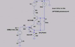
I've been taking a closer look (I placed my nose on the screen ) at the Super cascode.
Here are my conclusions, based in LTSpice:
- The upper transistor Ccb (Cob) shall be as low as posssible. This is a criteria for this transistor selection; idelly an RF type. But the RF transistors are usually low voltage...
- The only way I found to stabilise it is a cap between base and emitter of the lower transistor (see diagram).
Of course, BW will sulffer, how much depends on the specific transistor types.
Distortion wise, comparing a super with a conventional cascode, all else equal, the super has more second and less higher harmonics (more 'euphonic').
Note: I've simulated the PNP side since this was the one giving me trouble in the amp.
I've been taking a closer look (I placed my nose on the screen
) at the Super cascode.Here are my conclusions, based in LTSpice:
- The upper transistor Ccb (Cob) shall be as low as posssible. This is a criteria for this transistor selection; idelly an RF type. But the RF transistors are usually low voltage...
- The only way I found to stabilise it is a cap between base and emitter of the lower transistor (see diagram).
Of course, BW will sulffer, how much depends on the specific transistor types.
Distortion wise, comparing a super with a conventional cascode, all else equal, the super has more second and less higher harmonics (more 'euphonic').
Note: I've simulated the PNP side since this was the one giving me trouble in the amp.
Attachments
Revised amp
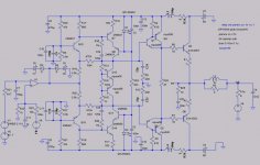
Thank's to Andy's help with models, here's a revised version of the circuit - better compensation and no weird cross conduction atifafcts!
To speed up simulations, L2, R24 and L4, R26 were shorted and C9, C14 were reduced to 100n.
These components only have impact in PSRR measurements.
V7, V8, D3, D4 were added as clamps because sometimes the circuit would not converge (so the ideal opamp would be more like a real one).
Now, CCIR IM (19K&20K, 80V PP) in band components are under -120dB, and so are interface distortion ones.
The slew rate is less than I would like...
Attachments
Hello, guys,
If you're still following this thread...
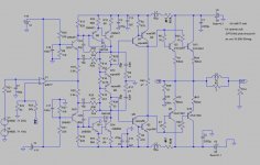
Another revision.
Parallel power transistors to improve 4 ohms operation, better thermal comp, the cascode is gone, finer compensation, feeding the bases of the input transistors from the regulated opamp supply, clamp diodes to improve clipping, a 50Mhz opamp (real model now).
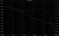
NFB at 20kHz almost 65dB, phase margin 55deg/15 dB.
The big question - how close to real world it is? Or is it just an expensive oscillator?
The AD817 has a significant input current; this will make it almost impossible to use a pot at the input.
Any suggestion of other similar opamp in DIP?
Thanks,
If you're still following this thread...
Another revision.
Parallel power transistors to improve 4 ohms operation, better thermal comp, the cascode is gone, finer compensation, feeding the bases of the input transistors from the regulated opamp supply, clamp diodes to improve clipping, a 50Mhz opamp (real model now).
NFB at 20kHz almost 65dB, phase margin 55deg/15 dB.
The big question - how close to real world it is? Or is it just an expensive oscillator?
The AD817 has a significant input current; this will make it almost impossible to use a pot at the input.
Any suggestion of other similar opamp in DIP?
Thanks,
Attachments
yes, we are hereIf you're still following this thread...
at lastthe cascode is gone
let me think aboutclamp diodes to improve clipping
also I hadn't checked yor frequency compensation
-why do you use R29 R28 (I know the answer, pls provide your own opinion
)-change bias (Q9 Q12) to Sziklai
-remove Sziklai from driver (simple triple EF)
-use stacked supplies
-use op amp with JFET input
-enjoy

dimitri said:
-why do you use R29 R28 (I know the answer, pls provide your own opinion
-change bias (Q9 Q12) to Sziklai
-remove Sziklai from driver (simple triple EF)
-use stacked supplies
-use op amp with JFET input
-enjoy
Hello, Dimitri
- R28/29 - to improve thermal compensation (see the .temp statement - actually I went to higher temps). Better than without them.
- I did not place the bias in the Sziklai because of the higher driver current, but have not tested it.
- Why not the Sziklai? One more Vbe in the path to distort, thermal compensate...
- By stacked supplies you mean a V++ to the drivers? Maybe.
- JFET opamp w/ 50Mhz BW? can you suggets one in DIP?
- Thanks!
- Status
- This old topic is closed. If you want to reopen this topic, contact a moderator using the "Report Post" button.
- Home
- Amplifiers
- Solid State
- Comments on Intelectual creation, pls