Hi, I have the following scenario. Look at my attached schematics, or part of it.
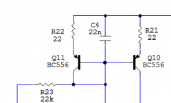
Q10 is driven with 10mA bias. Vce is 0.62V.
I got suspicious to my simulations about the actual collector impedance at that low voltage and made a little test circuit. The result was 17kohm and that's a bit too low for my application. My simulator reports over 150k, and that's a reasonable figure if Vce could be raised just one more volt.
Now, does anyone know of some transistor type that performs better from that point of view. Perhaps a low voltage type. It must be a "through hole" type.
Thankful for advises.
Attachments

Maybe the images and tables in (this diyAudio thread) might give you some ideas.
As a very VERY rough guideline, "collector impedance" in your circuit will be approximately 8 * (Vearly / 10mA). So you seek a PNP device with Vearly > 190 and with a well-behaved I-V curve at Vce=0.6 volts.
The factor of 8 comes from emitter degeneration resistor R21. (R21 * gm) = 8.4.
As a very VERY rough guideline, "collector impedance" in your circuit will be approximately 8 * (Vearly / 10mA). So you seek a PNP device with Vearly > 190 and with a well-behaved I-V curve at Vce=0.6 volts.
The factor of 8 comes from emitter degeneration resistor R21. (R21 * gm) = 8.4.
Perhaps the plots of current vs voltage would be useful to study.
When you hover your cursor over a thumbnail image, you can read its filename. The transistor part# is embedded in the filename.
The table of "knee voltages" in post #60, and the plots in 60-62, might be illuminating as well.
When you hover your cursor over a thumbnail image, you can read its filename. The transistor part# is embedded in the filename.
The table of "knee voltages" in post #60, and the plots in 60-62, might be illuminating as well.
Last edited:
OK, I thought it was quasi saturated but I increased Vce to 2.5V and the impedance was only slightly higher. So it's probably the early value that's should be high.
I seek some kind of magic transistor since the hfe should be at least 300 as well.
So according to your measurements, the ZTX seems well suited. High early value, low saturation knee and also a high hfe. The ZTX family seems to be some sort of "Rolls Royce" of BJT's - they are quite good at everything.
selecting good Q helps, but composite topologies can give bigger boosts
various enhancemts are possible, cascode with base current cancellation, Hawksford shows many but is poor on priority of these circuits
https://web.archive.org/web/2013012..._lab/malcolmspubdocs/J10 Enhanced cascode.pdf
various enhancemts are possible, cascode with base current cancellation, Hawksford shows many but is poor on priority of these circuits
https://web.archive.org/web/2013012..._lab/malcolmspubdocs/J10 Enhanced cascode.pdf
jcx: selecting good Q helps, but composite topologies can give bigger boosts
With Vce=0.62V and another 0.22V across R21, you've got 0.84V of total headroom to build a toprail current mirror with 10mA input, 10mA output, and output impedance > 150K. What composite topology is suitable?
With Vce=0.62V and another 0.22V across R21, you've got 0.84V of total headroom to build a toprail current mirror with 10mA input, 10mA output, and output impedance > 150K. What composite topology is suitable?
Attachments
I have figured it out even more.
It's just to insert a cascode. Then the early effect may be very big so the degeneration resistor may be reduced to some 10 ohm.
Then each transistor will have 0.4V to play with. If I use BC560C, then eventual beta droops will be manageable.
But there is an annoying fact. I have just ordered a batch of PCB's from China...
When I sent the order, I anticipated to find something to alter. It's inevitable.
Another function performed by the emitter degeneration resistors is: reducing the effect of VBE mismatch between Q10 and Q11. This gives a higher precision match between Iin (Q11) and Iout (Q10). But perhaps you don't care if Iout differs from Iin by (for example) 5% or 10%.
- Status
- This old topic is closed. If you want to reopen this topic, contact a moderator using the "Report Post" button.
- Home
- Amplifiers
- Solid State
- Collector impedance