Since my script is based on William Cowans work, ill post a link to his website, where he has posted a good picture to understand the layout. My mods are this: In his picture the rear / front of the driver taps into the horn directly. In my script, the rear and the front of the driver are connected to two compression chambers of equal size which tap into the horn like the driver in Williams pic. Then i connected two resonators, with their open end directly at the driver rear (the part which is deep in the horn - in the pic it is where a2 is). Last mod is a big duct, the size of your room, which follows the last th segment. This duct has standing waves just like a real room and its damping can be adjusted to bring the room modes to the attention if the viewer.
Link to Williams picture:
http://www.cowanaudio.com/images/akabak2.gif
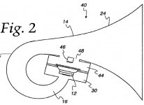
Here is a pic from Toms patent, which shows the compression chambers, but lacks one part of the horn path (a1-a2 in williams pic).
Link to Williams picture:
http://www.cowanaudio.com/images/akabak2.gif
Here is a pic from Toms patent, which shows the compression chambers, but lacks one part of the horn path (a1-a2 in williams pic).
Attachments
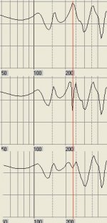
More study on resonators. The first plot shows a peak at 230Hz.
The second is affected by a duct, thus:
Duct 'D1' Node=3=0 dD=10cm Len=36cm
I couldn't get too much better using a simple duct.
The third uses damping in the duct (thanks MaVo)
Duct 'D1' Node=3=0 dD=15cm Len=36cm QD/fo={0.05}
The second is affected by a duct, thus:
Duct 'D1' Node=3=0 dD=10cm Len=36cm
I couldn't get too much better using a simple duct.
The third uses damping in the duct (thanks MaVo)
Duct 'D1' Node=3=0 dD=15cm Len=36cm QD/fo={0.05}
Attachments
@ pinkmouse: A good way to understand akabak scripts is to use pen and paper, draw every node in the script on the paper, perhaps with a nice circle around it. the you go through every line of the script and whenever you see that an element (for example a duct or waveguide) connects two nodes (for example Duct 'd1' Node=20=21) then you connect the nodes with a line and tag this line with the element. in this case you connect node 20 and 21 and write d1 or duct1 near it. this way, you will get a map of the system. once you have it, you can see on which ways the sound will flow.
@jnb: How can we achieve this kind of damping? do we stuff the pipe with rockwool or something like that? what kind of damping can affect those big wavelengths in question? But absorption seems to be a good way to make the q broader.
@jnb: How can we achieve this kind of damping? do we stuff the pipe with rockwool or something like that? what kind of damping can affect those big wavelengths in question? But absorption seems to be a good way to make the q broader.
I assume Akabak models its damped ducts as for normal stuffing. The manual says it's frequency independent but reality should only be some trial and error away.
I see this as like snubbing diodes. Some use just capacitors, but it really wants a resistor in there to produce heat and lose the energy.
I see this as like snubbing diodes. Some use just capacitors, but it really wants a resistor in there to produce heat and lose the energy.
Well, in reality, getting results with resonators will probably be easy. Tom showed in his DTS20 that the concept works. So, all one has to do, is to make a connection point reachable in the horn to connect a quarter wave resonator. Then one can experiment with different diameters, lengths and stuffing, to get the best real life results.
One other thing, do you have a clue, what effect the damping material in the DTS20 has? I mean, it is so thin, it couldnt have an effect on the generated sound, or am i wrong?
One other thing, do you have a clue, what effect the damping material in the DTS20 has? I mean, it is so thin, it couldnt have an effect on the generated sound, or am i wrong?
AkAbak TH's for Dummies
Sorry if this seems a bit rushed, but MaVo was starting to "cut the grass right before my feet", so I had to put some pace to it.
I hope people will enjoy this short tutorial (more like an extensively commented script) and that I succeed in my aim to Kickstart people into AkAbak.
| OK, welcome to this AkAbak Tapped Horn for Dummies tutorial.
| (BTW, this is a working script with PLENTY of comments! ;-)
|
| An AkAbak script consists of roughly 2 parts: a definitions part, and
| a system part. The first should be very straightforward, while the latter
| can be visualized as a "string" of elements that make up the speaker
| that is being modelled. These elements are connected with Nodes.
| The result is that these elements have (at least) an entrance and an exit.
| Therefore, by appropriately choosing numbers for the entrance node and
| the exit node of each element, we build our string/system by choosing
| the same number for the exit node of one element, and the entrance node
| of the next one, thereby effectively joining them.
|
| First lets look at the driver. I choose a Monacor SPH-212, a 8" driver for
| bass-reflex cabinets that I have playing here next to me.
|
| Go to Help > Index > Search , type "Driver" and press enter. Then choose
| "Driver - Network Element" from the list below and double click it.
| For this tutorial, the following part from the Parameter list is important:
| "Node=s=t=u=v Four pole (Def_Driver, Def_PiezoDriver)
| The connection terminals of the driver are between poles s and t. The phase
| position of the radiated sound is inverted if the poles s and t are
| exchanged. Pole u is the front of the diaphragm, pole v its rear."
| So if we click the examples link above, we see in 1) how we must fill in the
| nodes of the driver element once we get to the System part of the script.
|
| Go back to the Driver element page and click the Def_Driver link.
| Here we see a parameter list. You'll recognize many of the T/S parameters
| you also have to fill in if you use HornResp.
| Check out the Conical Diapraghm by clicking on the examples link above. The
| text does a good explanation of what the numbers in the example are for.
| Now lets fill in our first part of the script!
|
| In the example window, click Edit > Copy ... and copy-paste the Conical
| Diapraghm definition example in your script. Adjust the parameters to fit
| your driver - or as in this tutorial, the SPH-212 - as below:
Def_Driver 'SPH-212'
dD=21,2cm dD1=6,5cm tD1=2,5cm |Cone
fs=30Hz Vas=82L
Qms=2,21 Qes=0,5 Re=6,2ohm Le=0,6mH
| Now we have defined the driver we will use in our system, so lets go to
| build the actual "string" of elements itself. To do so, we type:
System 'RLDCTH'
| We start with the beginning of all things, namely the driver. As already
| explained with the Driver - Network Element part above, we must choose our
| node numbers like this:
Driver Def='SPH-212'
Node=1=0=200=300
| So we remember that the first 2 nodes tell AkAbak how the electricity goes
| and the last 2 nodes give numbers to respectively the front and the rear
| of the diaphragm.
| (Also don't forget to get the name of the driver correct, in case you have
| given it an other name in the definitions part on top of the script.")
|
| Now we must make the connection from the front of the driver to our Tapped
| Horn. We will do this with a compression chamber. Check out the
| Duct - Network Element in the help file for this, especially the Parameter
| list where you can see how to define/number the Nodes. You'll see with the
| nodes that there is a clear entrance and exit to the element. Copy-paste
| the Air Chamber example into your script, but forget about the Radiator,
| since we aren't at the exit of the enclosure yet. Adjust as below:
Duct 'FrontCompchamber'
Node=200=201
sD=0,0200m2 Len=1cm Vf=8L
| So here we see the base of our system: we named the front of the driver
| (node) 200, and the output from this enters the duct element at (node) 200.
| The exit of the duct element is node 201, so this is the node we will have
| to connect our next element to.
| The duct itself is 1cm long and is 200cm^2 wide. If we would make this
| 100cm^2, we would have a compression rate of about 2, since the surface
| area of the driver is 218cm^2 and the duct/passageway to the TH reduces
| this to only half of the area.
| Vf is specified, so there is a 8L compression chamber at the entrance of
| the duct.
|
| The exit of the Duct element (Node 201) enters our TH and drives it. We
| will use the Waveguide - Network element (check the Help file) for our
| TH. As you will read in the help file, a Waveguide is much like a Duct,
| but with a changeing crosssectional area. The main difference with a horn
| is that in AkAbak the Horn element has a built-in Radiator element to
| couple the exit/mouth to the outside air. For this reason we will use the
| horn for the last part of our system.
Waveguide 'Conical Horn'
Node=201=301
STh=0,0200m2 SMo=0,0250m2
Len=290cm Conical
| The Waveguide has node 201 (exit of the "compression" Duct) as entrance
| and exits at 301 after 350cm. The throat is expanded from 200cm^2 till
| 300cm^2 at the mouth, according to a conical expansion rate.
|
| Now what happened to the back of the driver? Well, at node 300 it's still
| waiting for us to do something with it, so analoguous to the front
| compression chamber, we connect a Duct network element from node 300 till
| 301 :
Duct 'BackCompchamber'
Node=300=301
sD=0,01m2 Len=1cm Vf=20L
| Here we see we have used the same node (301) as the exit of our Waveguide!
| So now the back of the driver - trough the back compression chamber -
| drives our horn at the mouth, hence a Tapped Horn!
| You'll also notice the compression ratio is higher and the compression
| chamber is larger than in the front. Feel free to alter its values, but
| with the idea in mind that a compression chamber acts like a low pass
| filter and that node 301 is more close to the exit of the TH, I want to
| filter out high frequencies where they could interfere the most. Therefore
| I choose a smaller cross sectional area and a larger volume.
|
| Now all that is left is to couple the output of the system to the outside
| air. Normally we would use a Radiator network element, but since we still
| have a small part of the TH extending past the "tap" (node 301), we will
| use a Horn network element, which is - as already explained - a Waveguide
| and Radiator lumped together. The Help file makes this next element
| straightforward:
Horn 'Endhorn'
Node=301
STh=0,0250m2 SMo=0,100m2
Len=70cm T=1
| In this tutorial we have seen how to build a system by glueing different
| elements together by nodes. It is easily seen how one can make a standard
| cabineth by connecting an Enclosure element to the back of the driver. (Or
| from there on a standard horn if we add a Horn element to the front node.)
| To create a Bass-reflex, one could attach a Duct element to the rear node
| and use Vf for the enclosure/compression chamber size. (Don't forget to add
| a radiator element to the other end of the tube.)
|
| As long as you visualize the system as a bunch of ropes (with tags on it)
| and then connect the different ends of the ropes together like you do with
| the nodes, you can build the system you want. Use the help file for
| details on which parameters that affect the elements.
|
|
| To simulate 1/4th or 1/8th space loading, check out the Def_Reflector
| examples in the help file and put your desired one on top of the script
| in the Definitions part. Adjust the parameters as needed.
| Don't forget to put the "Reflection" keyword in the element that is
| subject to it. (In this script it is the Horn network element, which is
| the only one to radiate into the room.)
|
|
|
| One last exercise to the reader: How would you make 1/4WL resonators?
|
|
|
| Duct elements that are closed on one end, will do the job fine. As you'll
| see in the help file, you can enter "=0" for the closed end-node,
| like this:
|
|
| Duct 'Res'
| Node=201=0
| dD=15cm Len=36cm
| QD/fo={0.05}
|
|
| Dependant on where you want to put the resonator(s), you alter the entrance
| node(s). (Which is at the Tapped Horn throat in this example.)
| QD/fo= ... is a variable that is dependant on stuffing in the tubes. Some
| experimentation will be needed to find an appropriate value that simulates
| your stuffing.
Sorry if this seems a bit rushed, but MaVo was starting to "cut the grass right before my feet", so I had to put some pace to it.
I hope people will enjoy this short tutorial (more like an extensively commented script) and that I succeed in my aim to Kickstart people into AkAbak.
| OK, welcome to this AkAbak Tapped Horn for Dummies tutorial.
| (BTW, this is a working script with PLENTY of comments! ;-)
|
| An AkAbak script consists of roughly 2 parts: a definitions part, and
| a system part. The first should be very straightforward, while the latter
| can be visualized as a "string" of elements that make up the speaker
| that is being modelled. These elements are connected with Nodes.
| The result is that these elements have (at least) an entrance and an exit.
| Therefore, by appropriately choosing numbers for the entrance node and
| the exit node of each element, we build our string/system by choosing
| the same number for the exit node of one element, and the entrance node
| of the next one, thereby effectively joining them.
|
| First lets look at the driver. I choose a Monacor SPH-212, a 8" driver for
| bass-reflex cabinets that I have playing here next to me.
|
| Go to Help > Index > Search , type "Driver" and press enter. Then choose
| "Driver - Network Element" from the list below and double click it.
| For this tutorial, the following part from the Parameter list is important:
| "Node=s=t=u=v Four pole (Def_Driver, Def_PiezoDriver)
| The connection terminals of the driver are between poles s and t. The phase
| position of the radiated sound is inverted if the poles s and t are
| exchanged. Pole u is the front of the diaphragm, pole v its rear."
| So if we click the examples link above, we see in 1) how we must fill in the
| nodes of the driver element once we get to the System part of the script.
|
| Go back to the Driver element page and click the Def_Driver link.
| Here we see a parameter list. You'll recognize many of the T/S parameters
| you also have to fill in if you use HornResp.
| Check out the Conical Diapraghm by clicking on the examples link above. The
| text does a good explanation of what the numbers in the example are for.
| Now lets fill in our first part of the script!
|
| In the example window, click Edit > Copy ... and copy-paste the Conical
| Diapraghm definition example in your script. Adjust the parameters to fit
| your driver - or as in this tutorial, the SPH-212 - as below:
Def_Driver 'SPH-212'
dD=21,2cm dD1=6,5cm tD1=2,5cm |Cone
fs=30Hz Vas=82L
Qms=2,21 Qes=0,5 Re=6,2ohm Le=0,6mH
| Now we have defined the driver we will use in our system, so lets go to
| build the actual "string" of elements itself. To do so, we type:
System 'RLDCTH'
| We start with the beginning of all things, namely the driver. As already
| explained with the Driver - Network Element part above, we must choose our
| node numbers like this:
Driver Def='SPH-212'
Node=1=0=200=300
| So we remember that the first 2 nodes tell AkAbak how the electricity goes
| and the last 2 nodes give numbers to respectively the front and the rear
| of the diaphragm.
| (Also don't forget to get the name of the driver correct, in case you have
| given it an other name in the definitions part on top of the script.
|
| Now we must make the connection from the front of the driver to our Tapped
| Horn. We will do this with a compression chamber. Check out the
| Duct - Network Element in the help file for this, especially the Parameter
| list where you can see how to define/number the Nodes. You'll see with the
| nodes that there is a clear entrance and exit to the element. Copy-paste
| the Air Chamber example into your script, but forget about the Radiator,
| since we aren't at the exit of the enclosure yet. Adjust as below:
Duct 'FrontCompchamber'
Node=200=201
sD=0,0200m2 Len=1cm Vf=8L
| So here we see the base of our system: we named the front of the driver
| (node) 200, and the output from this enters the duct element at (node) 200.
| The exit of the duct element is node 201, so this is the node we will have
| to connect our next element to.
| The duct itself is 1cm long and is 200cm^2 wide. If we would make this
| 100cm^2, we would have a compression rate of about 2, since the surface
| area of the driver is 218cm^2 and the duct/passageway to the TH reduces
| this to only half of the area.
| Vf is specified, so there is a 8L compression chamber at the entrance of
| the duct.
|
| The exit of the Duct element (Node 201) enters our TH and drives it. We
| will use the Waveguide - Network element (check the Help file) for our
| TH. As you will read in the help file, a Waveguide is much like a Duct,
| but with a changeing crosssectional area. The main difference with a horn
| is that in AkAbak the Horn element has a built-in Radiator element to
| couple the exit/mouth to the outside air. For this reason we will use the
| horn for the last part of our system.
Waveguide 'Conical Horn'
Node=201=301
STh=0,0200m2 SMo=0,0250m2
Len=290cm Conical
| The Waveguide has node 201 (exit of the "compression" Duct) as entrance
| and exits at 301 after 350cm. The throat is expanded from 200cm^2 till
| 300cm^2 at the mouth, according to a conical expansion rate.
|
| Now what happened to the back of the driver? Well, at node 300 it's still
| waiting for us to do something with it, so analoguous to the front
| compression chamber, we connect a Duct network element from node 300 till
| 301 :
Duct 'BackCompchamber'
Node=300=301
sD=0,01m2 Len=1cm Vf=20L
| Here we see we have used the same node (301) as the exit of our Waveguide!
| So now the back of the driver - trough the back compression chamber -
| drives our horn at the mouth, hence a Tapped Horn!
| You'll also notice the compression ratio is higher and the compression
| chamber is larger than in the front. Feel free to alter its values, but
| with the idea in mind that a compression chamber acts like a low pass
| filter and that node 301 is more close to the exit of the TH, I want to
| filter out high frequencies where they could interfere the most. Therefore
| I choose a smaller cross sectional area and a larger volume.
|
| Now all that is left is to couple the output of the system to the outside
| air. Normally we would use a Radiator network element, but since we still
| have a small part of the TH extending past the "tap" (node 301), we will
| use a Horn network element, which is - as already explained - a Waveguide
| and Radiator lumped together. The Help file makes this next element
| straightforward:
Horn 'Endhorn'
Node=301
STh=0,0250m2 SMo=0,100m2
Len=70cm T=1
| In this tutorial we have seen how to build a system by glueing different
| elements together by nodes. It is easily seen how one can make a standard
| cabineth by connecting an Enclosure element to the back of the driver. (Or
| from there on a standard horn if we add a Horn element to the front node.)
| To create a Bass-reflex, one could attach a Duct element to the rear node
| and use Vf for the enclosure/compression chamber size. (Don't forget to add
| a radiator element to the other end of the tube.)
|
| As long as you visualize the system as a bunch of ropes (with tags on it)
| and then connect the different ends of the ropes together like you do with
| the nodes, you can build the system you want. Use the help file for
| details on which parameters that affect the elements.
|
|
| To simulate 1/4th or 1/8th space loading, check out the Def_Reflector
| examples in the help file and put your desired one on top of the script
| in the Definitions part. Adjust the parameters as needed.
| Don't forget to put the "Reflection" keyword in the element that is
| subject to it. (In this script it is the Horn network element, which is
| the only one to radiate into the room.)
|
|
|
| One last exercise to the reader: How would you make 1/4WL resonators?
|
|
|
| Duct elements that are closed on one end, will do the job fine. As you'll
| see in the help file, you can enter "=0" for the closed end-node,
| like this:
|
|
| Duct 'Res'
| Node=201=0
| dD=15cm Len=36cm
| QD/fo={0.05}
|
|
| Dependant on where you want to put the resonator(s), you alter the entrance
| node(s). (Which is at the Tapped Horn throat in this example.)
| QD/fo= ... is a variable that is dependant on stuffing in the tubes. Some
| experimentation will be needed to find an appropriate value that simulates
| your stuffing.
For anyone interested, the 6" Tang Band driver that Volvotreter used in his mini-TH is in the latest PartsExpress flyer on sale for $29. This price isn't yet reflected on the web site, though.
I (of course) ordered two yesterday morning before receiving the flyer; I've emailed PE support to see whether they'll honor the price retroactively.
I'm hoping to get to start building two of Volvotreter's designs this weekend; I'm taking Friday off for a long weekend of audio, but acoustic treatments are first up, so I may not get to the subs.
1139
Yoo All
Don't be to quick to order the 1139 on sale right now.The TB that is in Volvotreters tapped horn are not sold by PE.Drivers used in Volvotreters tapped horns are 1139SC and 1139SG
PE is 1139SI not sure where to get T/S for these as the TB webside does not show them either.
Maduras
Yoo All
Don't be to quick to order the 1139 on sale right now.The TB that is in Volvotreters tapped horn are not sold by PE.Drivers used in Volvotreters tapped horns are 1139SC and 1139SG
PE is 1139SI not sure where to get T/S for these as the TB webside does not show them either.
Maduras
Re: 1139
http://www.diyaudio.com/forums/showthread.php?postid=1420907#post1420907
GM
maduras said:Yoo All
Don't be to quick to order the 1139 on sale right now.
http://www.diyaudio.com/forums/showthread.php?postid=1420907#post1420907
GM
Tapped horn vs. reflex comparison
I've been doing some comparisons in the last few days using Hornresp with some very interesting results...
One conclusion is that tapped horns aren't really horns, they're resonant systems like a reflex or bandpass box but with different tradeoffs. True horns provide a largely resistive acoustic load to the driver (high real acoustic impedance in Hornresp) which gives very high efficiency with reduced cone travel and flat response with little sensitivity to driver parameters, but tapped horns do nothing of the sort.
This can also be seen if you look at the electrical impedance and what the cone travel and acoustic impedance are doing; tapped horns have impedance minima (like a reflex) where the cone doesn't move, and impedance maxima where the movement is just damped by back EMF.
Like a reflex box, the output at the impedance minima is proportional to (BL/area), the output at the impedance maxima is proportional to (area/BL) -- so like a reflex (and unlike a true horn) the frequency response flatness is very sensitive to driver parameters, especially BL.
The only real difference is that the reflex has 2 impedance peaks with a minimum in between at the tuning frequency, the tapped horn has three peaks with 2 minima in between (and some more peaks higher up).
After a lot of tweaking I've come up with what I think are 2 closely optimised designs, one tapped horn and one reflex, which have almost identical performance but need very different drivers.
The tapped horn uses one TC Sounds PA-5100 (which they never really launched); this used a radial neo motor like the Aura 1808 but a lot stronger (BL=25.6, Re=3, Mmd=318, Xmax=18mm), was billed as handling 1500Wrms, and projected to cost about $800. Note that the equivalent BL for an 8 ohm driver would be 36 which is almost unheard of...
The horn is 330cm long total (tap points 20cm from each end) with S1=330cm2 (3.5:1 compression ratio -- Al cone is *very* strong) and S3=2500cm2, total box volume is 420l. Impedance peaks are at 33Hz and 66Hz, dips are at 44Hz and 94Hz -- if BL is varied by +/-20% then the response ripple is 3dB one way or the other between impedance min and max, which explains why it's so difficult to find the "right" driver.
The reflex uses 2 BMS18N850V2 neo drivers (BL=26, Re=6, Mmd=240, Xmax=16mm) which handle 1200Wrms each and cost about $400 each (same total as the TC driver). The box is 280l internal (310l total including ports) tuned to 32Hz.
Efficiency (2pi) is 100dB/W (4 ohms nominal) for the tapped horn, 99dB/W (4 ohms) for the reflex -- which is 20% smaller, so a box the same size as the tapped horn with slightly different drivers would be 1dB more efficient at 100dB/W i.e. exactly the same as the tapped horn. Both boxes are -3dB at 32Hz and flat up to 100Hz, the tapped horn has two nasty +7dB peaks at 130Hz and 190Hz.
With 2000W into the tapped horn peak output is 133dB, peak cone travel is +/-17mm which is just inside Xmax. With 2400W into the reflex (1dB less efficient because it's smaller) peak output is 133dB, peak cone travel is +/-15.7mm which is just inside Xmax.
So for the same size box both tapped horn and reflex have the same efficiency, same maximum output, same distortion (cone travel is the same).
The tapped horn needs one very high-end 18" driver (this BL/Re is exceptional), the reflex needs 2 high-end 18" drivers which cost about the same.
The tapped horn is hard to design and build and very sensitive to driver parameters, and has nasty peaks in the 100-200Hz region.
The reflex is easy to design and build and less sensitive to the driver, and is flat to several hundred Hz.
Given this comparison it's not clear what the real advantage of the (single-driver) tapped horn is over a (twin-driver) reflex, *assuming* you can get suitable drivers to build an optimised version of both (which may not be the case for one or both boxes) -- in fact most of the plus points seem to be on the side of the reflex.
I've done several similar comparisons and the result always ends up similar -- the tapped horn needs one high-BL high-Mmd driver, the reflex needs two lower-BL lower-Mmd drivers with double the total displacement, but the overall box size and efficiency are pretty much identical. This shouldn't come as a surprise because they're both multi-resonant systems, so the same laws apply to both.
It's true what Tom Danley said that cone travel is reduced by a tapped horn and output *for one driver* is increased. The figures show that the reflex needs twice the driver displacement (2 drivers instead of 1 with similar Xmax) -- but these two drivers will handle more power then the one in the tapped horn, and certainly power compression will be lower, and they cost about the same (and the box is a lot cheaper to build).
I imagine there may be some comments about this...
Ian
P.S. Looking at tapped horn ripple vs. parameter variation I get the following changes from flat response at impedance min and max:
33Hz (Zmin) 44Hz (Zmax) 66Hz (Zmin) 94Hz (Zmax)
BL=25.6 (actual) --------------------------------------------------------------
BL=30 +1.0 -1.3 +0.9 -1.0
BL=20 -2.0 +1.8 -2.2 +1.5
Mmd=318 (actual) ------------------------------------------------------------
MMd=400 -0.3 +0.2 -0.7 +1.4
Mmd=250 +0.2 -0.3 +0.6 -1.2
Cms=6.8e-5 (actual) ---------------------------------------------------------
Cms=3.4e-5 +1.1 -0.9 +0.8 -0.7
Cms=1.3e-4 -0.5 +1.3 -0.4 +0.4
S1=320 (actual) --------------------------------------------------------------
S1=250 -1.7 +0.8 -0.4 +0.2
S1=400 +1.4 -0.8 +0.4 -0.3
S3=2500 (actual) ------------------------------------------------------------
S3=2000 -0.7 -0.8 -0.7 -1.4
S3=3000 +0.3 +0.6 +0.6 +1.1
L23=20 (actual) -------------------------------------------------------------
L23=40 +0.2 -0.2 -0.8 -0.1
L23=0 +0.7 -0.5 +0.5 -0.5
Conclusion is that ripple is sensitive to *everything", but especially BL -- compliance has least effect (figures were for large 2:1 variation either way from nominal), Mmd not much, tap point has significant effect, throat area is important, mouth area (= box volume) mainly affects overall sensitivity.
You need to be very lucky or have a lot of trial and error to get an optimum tapped horn -- I think Tom Danley would agree with this.
G'day Ian
This is a very interesting theoretical study, but from experience I'd have to say that something is amiss. I have built many subwoofers using almost all variants of the Peerless XLS/XXLS 12" drivers, in single dual and quad arrangements, sealed, ported and PR'd and I'd have to say that none of them, except perhaps the quad XXLS, come close in maximum output to the single 830564 30Hz tapped horn that is currently in my "B" system. I'm not sure that the tapped horn models we are using are accurately calculating excursion. I have thrown huge input powers into some of the tapped horns I've built, and excursion above cutoff is always low. Others have had the same experience.
Cheers
William Cowan
cowanaudio said:G'day Ian
This is a very interesting theoretical study, but from experience I'd have to say that something is amiss. I have built many subwoofers using almost all variants of the Peerless XLS/XXLS 12" drivers, in single dual and quad arrangements, sealed, ported and PR'd and I'd have to say that none of them, except perhaps the quad XXLS, come close in maximum output to the single 830564 30Hz tapped horn that is currently in my "B" system. I'm not sure that the tapped horn models we are using are accurately calculating excursion. I have thrown huge input powers into some of the tapped horns I've built, and excursion above cutoff is always low. Others have had the same experience.
Cheers
William Cowan
I'm pretty sure that most people would agree that Hornresp's predictions are pretty good, many people have said so. Just because the numbers are predictions doesn't mean they're wrong
I did say that the driver requirements are quite different for an optimum tapped horn and an optimum reflex; if a driver is just right for a tapped horn (which the 830564 looks like it could be going by your response plots) then it certainly won't be right for the twin-driver reflex equivalent, it will have too high BL and Mms which means lower output across the whole band.
The Hornresp simulations say that in the same sized box a tapped horn has the same efficiency, maximum output, cone travel and distortion as a reflex with two drivers, each with the same Xmax as the tapped horn driver but different parameters. This is Hoffman's Iron Law at work again -- the tapped horn is no magic bullet, it's another way of making a good speaker.
So you could say that the tapped horn gets 6dB more output out of one driver and halves the cone travel for a given output, both of which are perfectly correct as you (and Eva) have said.
You could also say that as far as the user's concerned they don't care what's inside the box (one driver or two), only the end result -- which is the same size, performance and cost for both boxes.
Ian
Hi
You guys have busy been I see.
Iand said ” So you could say that the tapped horn gets 6dB more output out of one driver and halves the cone travel for a given output, both of which are perfectly correct as you (and Eva) have said.
You could also say that as far as the user's concerned they don't care what's inside the box (one driver or two), only the end result -- which is the same size, performance and cost for both boxes.”
A few thoughts, one can get at least 9+ dB of acoustic gain (so far) over a direct radiator version using the same drive depending on the Tapped horn and driver.
That 9dB corresponds to an added acoustic load which cuts excursion to about 1 / 3 as well.
Also, while there are times one can generate parameters that would do the job, getting a driver made with those parameters is another story, build able cone drivers only span a “range” of possibilities.
While the audibility of group delay is debated, keep in mind that the vented box is an inverter, it exhibits a 180 degree phase rotation going from the front to vent radiation.
The Tapped horn is a form of quarter wave resonator and so exhibits 90 degrees of rotation, half as much as the vented box of the same low corner F.
As some of the LF corner shape of a Taped horn (depending on its size) is set by the failing radiation resistance (and this frequency dependent resistance has little reactance associated with it), the measured GD is sometimes less than the response shape alone would predict.
Lastly, lets not forget the rarely mentioned problem that Vents are normally highly nonlinear and choke off well below rated power. With a Quarter wave horn, at the low cutoff, the motion at the throat is a minimum and maximum at the mouth (where its area is very large).
Take a whack at vented alignments that occupy the same internal volumes, same low corner F as these two. See how close one can come and what the driver’s parameters are like.
Keep in mind the response curves were measured at 100Watts drive (+20dB over 1 W) but at 10 meters (-20dB over 1 Meter) half space for a real and conservative measure of the 1W 1M spec (with out the error the physical displacement by cabinet causes measuring large enclosures).
http://www.danleysoundlabs.com/pdf/Danley TH Mini Spec Sheet_r2.pdf
http://www.danleysoundlabs.com/pdf/Danley TH-50 Spec Sheet r1.pdf
Best,
Tom Danley
G'day again Ian
Your argument for the drivers suitable for a Tapped Horn being twice the cost of a driver with suitable specs for a vented box does not hold water. Amongst the drivers I'm comparing, are the 830564 (very suitable in a 30Hz TH) 830877 (Great 20Hz TH driver) and the 830845/847 drivers that are excellent in Sealed/Vented boxes. All these drivers are around the same cost, with the 830877 being the cheapest of the lot. I guarantee I could make more 20Hz bass with a Tapped Horn using a 830877 than I could with any pair of these drivers in vented boxes. Driver cost would be half in this case, in favour of the Tapped Horn.
Sure you could buy a pair or quad of cheap drivers from another manufacturer and maybe, just maybe, reach a similar output level in a similar sized box with similar input power, but the price you'll pay will be higher levels of distortion because of the less advanced motor these drivers would use. This is where this modeling of yours falls apart, you are not comparing like drivers. Why don't you do your modeling again based on one family of drivers? I propose the XLS and XXLS series from Peerless because of the different sets of T/S parameters that are available with the same motor and inherent low distortion. All the drivers in this series are around the same price, too, give or take $20. They should be, it's only Mms and the compliance of the suspension that is being changed to get the different parameters. The price difference is more likely from the XXLS series spacer/different back plate and SVC/DVC, gold spring terminals on some models and rubber magnet boots on the automotive ones.
You've got to compare apples to apples to make a fair comparison.
Please don't take this the wrong way, I'm not trying to shoot you down, but just challenging your line of thought. I do appreciate the effort you have put in and some of your conclusions I believe are correct.
Cheers
William Cowan
- Home
- Loudspeakers
- Subwoofers
- Collaborative Tapped horn project