GM said:Parabolic?! In a prosound app seems like you'd want the max gain practical for a given bulk, which is the opposite of parabolic.
GM
I find that for a given total box volume, it's very often possible to get better results having a slower expansion in the first half (approximately) of the TH and a faster one in the second half -- Tom's patent also says this, and some of his commercial TH definitely do this.
This is simple to do in Hornresp by using a 4-section TH model (which I asked David to put in for exactly this reason), with 2 sections between the tap points. Then you can either model a zig-zag fold as built (constant rate of change of width) or choose any other expansion rate you want, matching the areas at 5 points (throat, throat tap. midpoint, mouth tap, mouth).
Each section of the TH now only has a relatively small expansion ratio (usually 2:1 or less), and the difference between parabolic/linear/conical profiles is then negligible.
Ian
P.S. David, can you make the tapped horn wizard also display total volume?
iand said:
I find that for a given total box volume, it's very often possible to get better results having a slower expansion in the first half (approximately) of the TH and a faster one in the second half -- Tom's patent also says this, and some of his commercial TH definitely do this.
...........the difference between parabolic/linear/conical profiles is then negligible.
Haven't read the patent, but for sure the best results is with the correct expansion for the BW and using theory to find it appears to work well according to HR. Not having seen any actual dimensioned construction drawings of any of DSL's THs I can only speculate, but sounds like you're describing the ~hyperbolic expansion I implied and I assume DSL uses, which is considerably different than parabolic/linear/conical profiles unless broken up into more than four segments.
GM
TB46: HornResp models conical segments, so the volume listed is in error if you build using
prismatic (parabolic) segments.
Danley has told us that, for the lowest two octaves, close is good enough. Unless you're
turning your horns on a lathe, you have no hope of building a true exponential horn ... And
just try to stuff a truly exponential horn into a simple box ... it can't be done.
Laying out a TH with a single fold and uniform taper (a la Cowan) from a HornResp sim is
a five minute job. Laying out a double fold TH with a uniform taper takes me about one-half
hour. When more than one taper is involved, the job can be much more complicated. Tom
Danley's LabSub is an approximation of an exponential horn, made of prismatic (parabolic)
segments. I'll bet it took Tom more than a week to lay it out, and it even has areas that have
negative taper
Remember, HornResp is a ONE-DIMENSIONAL simulation of a three dimensional horn. That's
why we are lucky that it works at all. The three dimensional equations are beyond computers.
Thanks to Tom Danley and David McBean,
~Don
Could you answer Don?
You may have already answered a question I had about TH design.
Perhaps you could clarify this for me:
Since every TH I have seen has been made with flat material ( OSB/Ply etc ) and the rate of expansion = one panel being "angled" - expansion in 1 direction - NOT 2 ( no compound angle cuts required ).
I thought this by definition eliminates some rates of expansion - for example exponential, tractrix?
As you said (?) You would have to be be able to fabricate a curve to qualify?
Syd
Don:HornResp models conical segments, ...Unless you're
turning your horns on a lathe, you have no hope of building a true exponential horn ... And
just try to stuff a truly exponential horn into a simple box ... it can't be done.
You may have already answered a question I had about TH design.
Perhaps you could clarify this for me:
Since every TH I have seen has been made with flat material ( OSB/Ply etc ) and the rate of expansion = one panel being "angled" - expansion in 1 direction - NOT 2 ( no compound angle cuts required ).
I thought this by definition eliminates some rates of expansion - for example exponential, tractrix?
As you said (?) You would have to be be able to fabricate a curve to qualify?
Syd
HK26147: If you build a horn out of many prismatic or conic segments, it can closely approximate an exponential (or any
other) horn. You can even approximate it with cubes, which by themselves have NO expansion, by using larger and larger cubes.
http://www.speakerstore.nl/index.php?l=en&pg=12&prjID=33
See: http://www.speakerstore.nl/constructions/steppedhorn/steppedhorn.jpg
The expansion of the segment does NOT limit the expansion of the horn.
Question?
~Don
JLH said:I think I know what is going on here now. I ended up splitting up the 259cm length and making this a 4 segment tapped horn. I was then able to use the tapped horn wizard and duplicate the measured response. The problem appears to be the flare rate in the throat is slower than what is in the model. This is the green area in the attached picture below. Also, the purple area has too fast of a flare rate, (i.e. it expands too fast). Lastly, it appears that the L34 segment is not 48cm long, but a bit too short. This could just be a case of not building something close enough to what was simulated.
JLH et all,
first, the picture perspective is misleading (I hope
") ), I will try to scan my pre-build drawings tomorrow.
), I will try to scan my pre-build drawings tomorrow.Second, I counted the end part and my full length includes the 90° arc to the exit... Is it wrong ?
Third, I have enlarged the driver hole today... No change in measurements...
I have glued and silliconed all joints that were not air tight...
No change in measurements either...
Fourth I have tested the sub "in-situ" quickly... It goes deeper indeep than my current floorstanding mains, but nothing breathtaking. At the same time, I have no other experience with any woofer and the test was quick.
What should I look for in my tests ?
Fith, I have not been able (whatever the settings) to feed the sub from the LFE output of my HT amp when listening to music. Reading the documentation, my impression was that some signal processing was happening for 2.0 signal as well, but it does not seem to be the case.
I must say that I am a bit depressed...
No, not that much
actually, just kidding, I know that "with a little help from my friends" I will get there in the end.Hi jm_kzo,
I noticed you're using your speaker setup in a smaller room?
Looks you've got a driver with a stiff suspension, (dried up?) rim?, causing Qm to peak and the Qts value to increase too, or is it a driver that missed the manufacture QC(quality control) a preliminary batch driver?.
If your T/S is reliable and if you can spend 10€ more on wood I suggest you to try an another approach that doesn't rely on sensitive expansion rates and behaves quite differently compared to a TH does but is much more forgiving if the implemented dimensions is a bit off.
You will lose some SPL sensitivity but I think still would provide quite adequate SPL:s considering your apparent room size.
If you place the port/termination in line, exactly in front of the driver instead of what HR shows the SQ IME improves too.
Look at the submitted picture 1(1) where you can find what you are trading for when building a TH in terms of speaker size / SPL and BW for the Beyma10G40.
Your T/S parameters resulted in a 121 L box in comparison to a corresponding smaller (53 L box) simple Tapped (stuffed) (straight) QWT (or TH) that would IMO perform well , with superior SQ and IME without the need for any series inductor.
b
1(1)
Attachments
Thanks Don; I figured that's what most TH builders were doing: basically approximation through multi segments.many prismatic or conic segments, it can closely approximate an exponential (or any
I didn't know;
(1) If anyone made TH's with some or all segments with a true curve, or if that was possible with this design?( fabrication difficulties not withstanding ).
(2) If TH design worked best with a constant expansion rate; Did it work better with a combination of segments and expansion rates?.
FWIW: Never having made one I would like to avoid the known pitfalls and dead ends and avoid reinventing or spinning wheels ( so to speak ). I have seen the struggles some have with getting the desired end results from their sims. I don't want to go through that, so I have contemplated going to a Non-Taped horn in the belief that the results would be more predicable.
Syd
HK26147: HornResp has been wonderful! Most problems have been accepting the manufacturers T/S numbers as fact or
air leaks.
1. Curves are not practical
2. TH's work fine with a single taper
Of all the Tapped Horns that I have done, along with Volvotreter, Cowan, Bell ... all of these have had a single taper. There's been a lot of talk about exponential, but I haven't seen any sawdust.
Danley's LabSub is a front loaded horn that's built up with 8 segments. All of the segments are prisms but the horn is
Exponential.
Attachments
Don Snyder said:HK26147: HornResp has been wonderful! Most problems have been accepting the manufacturers T/S numbers as fact or
air leaks.
1. Curves are not practical
2. TH's work fine with a single taper
Of all the Tapped Horns that I have done, along with Volvotreter, Cowan, Bell ... all of these have had a single taper. There's been a lot of talk about exponential, but I haven't seen any sawdust.
Danley's LabSub is a front loaded horn that's built up with 8 segments. All of the segments are prisms but the horn is
Exponential.
TH do work fine with a single taper -- but usually better with a two-stage one (slower/faster)
-- and it's very easy to try this with the 4-section TH wizard.If the horn is folded into 4 (up/down/up/down) the the resulting box is still rectangular since the tapers cancel (slow up/slow down/fast up/fast down).
If it's only folded once (long thin box) then a single taper is obviously easiest.
Ian
P.S. Single taper good -- double taper better! (thanks, George)
GM said:
Haven't read the patent, but for sure the best results is with the correct expansion for the BW and using theory to find it appears to work well according to HR. Not having seen any actual dimensioned construction drawings of any of DSL's THs I can only speculate, but sounds like you're describing the ~hyperbolic expansion I implied and I assume DSL uses, which is considerably different than parabolic/linear/conical profiles unless broken up into more than four segments.
GM
I meant that the difference within each section is negligible -- the overall taper is whatever you decide to make it for the 4 sections.
Ian
jm_kzo said:
my tests ?
Fith, I have not been able (whatever the settings) to feed the sub from the LFE output of my HT amp when listening to music. Reading the documentation, my impression was that some signal processing was happening for 2.0 signal as well, but it does not seem to be the case.
I would guess that it depends big time on your HT amp/processor. Mine has an option to cross-over and mix Main (L&R) with .1 (LF) or just feed the .1 LF to the sub. If you have no .1 source (2.0) you will need to mix yourself a sub channel OR use a separate crossover to extract low frequency info from the stereo feed. This could be low (line level) or speaker level (as seen in most plate amps).
Charles
==========================
Sunny Weetangera ACT
Don Snyder:accepting the manufacturers T/S numbers as fact or
Since I can measure driver T/S parms. and run impedance sweeps I would hope that would improve matters.
I received a lot of positive feedback and chronicles from Jim B and Mike...
I had pre(mis)conception of the design and wondered:
as said by Ian
TH do work fine with a single taper -- but usually better with a two-stage one (slower/faster)...
P.S. Single taper good -- double taper better!
Having been approached to build a car sub, I have contemplated using the "MCM 8" in the front loaded AT. The idea of a TH has been considered, but - As expressed prior...
I also have several JBL drivers ( 2206, 2226 ) whose specs I've measured, and I have an "itch" to put them to use.
Perhaps a TH Wiki is possible?
Thanks! Syd
bjorno said:Hi jm_kzo,
I noticed you're using your speaker setup in a smaller room?
Looks you've got a driver with a stiff suspension, (dried up?) rim?, causing Qm to peak and the Qts value to increase too, or is it a driver that missed the manufacture QC(quality control) a preliminary batch driver?.
Hi bjorno,
It is a PA driver, not much experience in this space, but I assumed they are all stiff. The driver is brand new.
I would not think it missed quality control (I hope it did not), I have 3 of them.
I have been told that breaking in those PA drivers takes time.
bjorno said:If your T/S is reliable and if you can spend 10€ more on wood I suggest you to try an another approach that doesn't rely on sensitive expansion rates and behaves quite differently compared to a TH does but is much more forgiving if the implemented dimensions is a bit off.
You will lose some SPL sensitivity but I think still would provide quite adequate SPL:s considering your apparent room size.
If you place the port/termination in line, exactly in front of the driver instead of what HR shows the SQ IME improves too.
Look at the submitted picture 1(1) where you can find what you are trading for when building a TH in terms of speaker size / SPL and BW for the Beyma10G40.
Your T/S parameters resulted in a 121 L box in comparison to a corresponding smaller (53 L box) simple Tapped (stuffed) (straight) QWT (or TH) that would IMO perform well , with superior SQ and IME without the need for any series inductor.
b
I would not trust my T&S parameters too much... I tend to doubt my measures at first
. The Claudio Negro site says that the driver should be really solidly attached. It was not really the case for me (not rigid enough mounting pod).I have a spare Beyma 10G40 to try for as long as I want (it is the one for my center speaker), I have not finished the mains yet fully, so the idea is to experiment, and I might well experiment your suggested QWT.
If I may ask, I assumed in the above that SQ stands for Sound Quality, IME for In My Experience, but what means QWT ?
I see from your design that it is just a straight pipe, but except it could start with Quater Wavelength, I must say that I am falling short of finding something for the T (I think I have BW and TH ok as well
).Thanks again for your interest in my project and help.
Re: JM's Beyma 10G40 TH
There's only so many things that can cause this.
1. Air leak - are you really sure it's sealed? Every single millimeter of it? Even around the driver?
2. Driver parameters - at some point you might want to confirm the value of vas, since it's pretty important. What is the reason you didn't finish the measurements and get vas? You did half the work, it's kind of like putting on only one shoe and going to work. Unfortunately, as I mentioned, if the driver specs you are using are wrong the only thing you can do is make a bigger box.
3. Hornresp design not properly translated to the physical box. In that case there's not much you can do either.
So you can see, if it's an air leak you can fix it. If it's not an air leak, IMO there's nothing you can do except find out the reason and avoid it next time. You could try a different driver but good luck with that, you'll need it if you try.
jm_kzo said:Guys, I have swapped the friver for one that is (more) broken in and had a few hours of 50/100/200Hz, but still the same... the 30-60Hz part is missing from the bandwidth.
There's only so many things that can cause this.
1. Air leak - are you really sure it's sealed? Every single millimeter of it? Even around the driver?
2. Driver parameters - at some point you might want to confirm the value of vas, since it's pretty important. What is the reason you didn't finish the measurements and get vas? You did half the work, it's kind of like putting on only one shoe and going to work. Unfortunately, as I mentioned, if the driver specs you are using are wrong the only thing you can do is make a bigger box.
3. Hornresp design not properly translated to the physical box. In that case there's not much you can do either.
So you can see, if it's an air leak you can fix it. If it's not an air leak, IMO there's nothing you can do except find out the reason and avoid it next time. You could try a different driver but good luck with that, you'll need it if you try.
JM's Beyma 140G40 TH
Guys,
as promised (and possibly to help you help me ) here is a sketch of my build.
I did that quickly as the one I really used is not readable by anyone else than me...
The measurements here assume a 0mm thick material, the real thing accounts for thickness of walls and internal partition.
The actual thing is 188 x 31 x 33.6 (the internal height is 30cm).
It should have been 188.7 tall, but the guy at Home Depot messed that one.
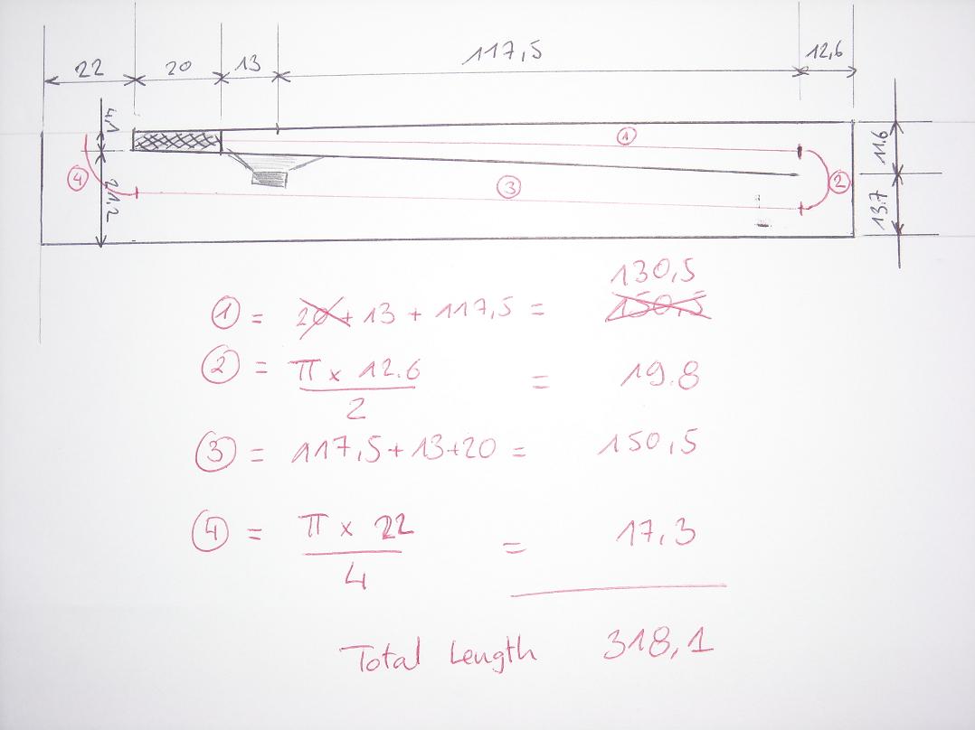
In red is the length calculation.
There is a wee bit of aproximation for the lengths 1 and 4 (the line is "angled", not parallel to walls and the diameter of arcs, but it should be pretty close.
I hope you can find to flawes here (at least I will know).
Many thanks.
Guys,
as promised (and possibly to help you help me
) here is a sketch of my build.I did that quickly as the one I really used is not readable by anyone else than me...
The measurements here assume a 0mm thick material, the real thing accounts for thickness of walls and internal partition.
The actual thing is 188 x 31 x 33.6 (the internal height is 30cm).
It should have been 188.7 tall, but the guy at Home Depot messed that one.
In red is the length calculation.
There is a wee bit of aproximation for the lengths 1 and 4 (the line is "angled", not parallel to walls and the diameter of arcs, but it should be pretty close.
I hope you can find to flawes here (at least I will know).
Many thanks.
Re: JM's Beyma 10G40 TH
Hi just_a_guy,
I am fairly sure abour air leaks... I do not feel any air around joints now.
Re measuring Vas, it is really the idea of glueing something to the cone that did put me off... and I did not have enough blue tack either (by a country mile)...
There is still a possibility that my hornresp calculation is not translated properly (to be honest, I hope it is the problem).
If this one does not work, I think I will default back to a proven design, TH or something else.
My mains have exhausted my taste for wild experiment and unexplored teritories.
Thanks anyway for your help and comments.
just a guy said:
There's only so many things that can cause this.
1. Air leak - are you really sure it's sealed? Every single millimeter of it? Even around the driver?
2. Driver parameters - at some point you might want to confirm the value of vas, since it's pretty important. What is the reason you didn't finish the measurements and get vas? You did half the work, it's kind of like putting on only one shoe and going to work. Unfortunately, as I mentioned, if the driver specs you are using are wrong the only thing you can do is make a bigger box.
3. Hornresp design not properly translated to the physical box. In that case there's not much you can do either.
So you can see, if it's an air leak you can fix it. If it's not an air leak, IMO there's nothing you can do except find out the reason and avoid it next time. You could try a different driver but good luck with that, you'll need it if you try.
Hi just_a_guy,
I am fairly sure abour air leaks... I do not feel any air around joints now.
Re measuring Vas, it is really the idea of glueing something to the cone that did put me off... and I did not have enough blue tack either (by a country mile)...
There is still a possibility that my hornresp calculation is not translated properly (to be honest, I hope it is the problem).
If this one does not work, I think I will default back to a proven design, TH or something else.
My mains have exhausted my taste for wild experiment and unexplored teritories
.Thanks anyway for your help and comments.
- Home
- Loudspeakers
- Subwoofers
- Collaborative Tapped horn project