Sabbelbacke said:Doing "free field" measurements gets harder the longer the wavelength ist. One good "trick" to get good results is the ground plane measuerement.
Putting the speaker on a hard surface like a parking space and putting the mik on the floor creates a situation where the floor acts as an acoustical mirror. If there is enough space between mic, box and surrounding objects (cars, buildings), one can easily do good measurements, especially for bass. I have no good online resource on the matter, but the book by Jospeh D'appolitto covers it in detail and it´s the method used by most sub-measurements.
Doing measurements in the horn mouth can have funny effects on the results.. I didn´t try it on a TH but know the effect on frontloaded horns quite good (and because I know measurements like this can be misleading, I never bothered again, always went straight to groundplane).
Hi Saddelbacke,
would you use "gated" measurement for this (like in SW) because my undertsanding is that that would indeed eliminate reflexions but they are no good for bass ?
I assume you would do this outdoor ?
That would be great if you could suggest dimensions for the set up ? How far to put the mike, how high above the ground, etc.
Many thanks in advance.
MartinQ said:jm_kzo, the first thing that comes to mind is:
- looks like it's made from particle board which is very flexible, is there any bracing?
- how thick is the material?
Hi Martin,
no bracing (again, I only experienced quite modest SPL... I think), this is just for experiment, if I build a final one, it will be braced.
This is 18mm particle board.
littlemike said:@ jm_kzo
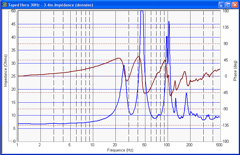
Can you measure impedance? That may help identify leaks.
Hi littlemike,
here are the impedance measurements...
littlemike said:
Some more questions:
How did you seal the top of the cabinet?
Is your microphone/preamp/measuring system accurate below 60 Hz?
Are you using any sort of response weighting in your mic preamp?
Are you measuring indoors?
Some answers (as much as I can)...
The top of the cabinet was screwed and I used foam joint (you know, for doors and windows) to improve sealing...
I do not really know if my measuring equipment is accurate. It is a Panasonic WM-61A mic and a "Eric Wallin" v2 preamp, but it never got calibrated. Can it be that off ?
I can borrow a digital SPL-Meter at the locakl Home Depot, would it be better ?
No response weighting either, how do you produce this ? Calibration ?
Yes, I am measuring indoors.
littlemike said:
Perhaps you could try measuring with FreqRespPlot or a another free swept-sine measurement software as a check of Speaker Workshop?
FreqRespPlot (in French)
There is an English version of the helpfile and software available too.
I think I will be Ok with the French version of Freqresplot
") .
. I have measured with REW and SyncRTA as well, measure more or less match.... unfotnately.
.Thanks for your help.
Low end Missing In Action
jm_kzo
Your measurement position is one part that is causing your problem. The horn mouth is designed to fired into a corner. The corner of the room then acts as an extension and thus an enlargement of the horn mouth. This will give better support for the low end of the frequency response.
For measuring check this out.
http://www.xlrtechs.com/dbkeele.com/papers.htm
You want #6.
It will tell you what to do. All I could do is quote from it so I might as well give you the source. As for the rest of the papers dig in!
Mark
Re: fb_TD10H
Is that the peaks in the passband or above? I'll be using computer eq anyway, not sure if there'll be problems or not.
Doom doom doom..... Hehe. What effect will a ratio of 4.35:1 have? S2 of 115 makes freq response not happy again.
In a related note, designing tapped horns does my head in - can anyone share (or make for me ) a TH with 10" driver that does 120db 35-90hz? All designs I've seen with 12" or less exceed xmax in this range.
Thanks all for your help
GM said:You may need one or more resonators to damp the peaks depending on the amount of stuffing used.
GM
Is that the peaks in the passband or above? I'll be using computer eq anyway, not sure if there'll be problems or not.
tb46 said:Hi,
The experts advise a compression ration below 3:1. In other words S2 should not be smaller than 115cm^2 for this driver. If you watch the comments bar at the bottom of the Hornresp input screen, it will tell you the compression ratio you are using.
Regards,
Doom doom doom.....
Hehe. What effect will a ratio of 4.35:1 have? S2 of 115 makes freq response not happy again. In a related note, designing tapped horns does my head in - can anyone share (or make for me
) a TH with 10" driver that does 120db 35-90hz? All designs I've seen with 12" or less exceed xmax in this range.Thanks all for your help
Keeles Paper focuses much on the nearfield measurements and primes for techniques how to convert a nearfield measurement into an farfield equivalent (combining Port Level and direkt radiation from the cone or taking the baffle step into account). I didn´t read it completely but recognise most of the grafix and topics and since its referenced a lot in later works, the topics are familiar.
As far as I´ve seen, ground plane measurements are not covered in this text.
A gated measurement would be no good with a subwoofer, since the time-window would be tooo long because of the very long wavelengths. Since groundplane measurements are +6dB than farfield halfspace, a 2m distance is a good starting point for "practical" measurements, since the level derived is comparable to normal measurements (2m is a doubling of distance to 1m which equals a 6dB loss, so you´re even). Also the distance to other objects is relevant, my rule of thumb is that objects need to be at least 3 times the distance than mic to speaker, some even say 5 times is necessary. Since I sometimes do those measurements in a Club-Discothek, the 2m/6m rule of thumb is a good enough compromise for me.
I also use sine-sweeps most of the times, since it´s signal to noise ratio is better for bass-measurements in suboptimal enviromnents. Look up farinas work on this, afaik he did the latest research on the matter.
I googled a little and found this, which might come in handy as a starting point:
http://www.mh-audio.nl/Groundplane.asp
Hope i could help.
Oh, I forgot, edit:
Measuring a cone and measuring a horn is not directly comparable. In front of a cone you´re always in the nearfield and have a pressure chamber-like situation. In a horn you have alternating perassure maxima and minima, so it is very likely to pick a different response at the hornmouth than if you´d measure outside the speaker. At least that´s i discovered in most of the cases when dealing with basshorns. A reflex(ported) enclosure always is easy to measure with keeles techniques, basshorns or TLs most of the time failed, but worked good with groundplane.
Re: My tapped horn experiment with a Beyma 10G40
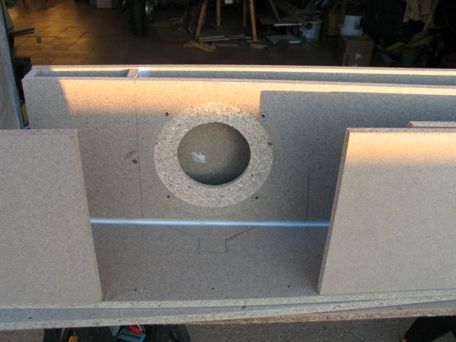
You need to make the hole opening into the throat the full size of the cone. The S2 area only concerns the horn, make the woofer hole as big as the cone. Your picture labeled "Where the driver will go..." shows me yor problem. I made the same mistake on my very first tapped horn. Do not feel bad, it looks like you have a big enough access panel to cut the woofer opening larger.
Rgs, JLH
jm_kzo said:Hi tapped horn gurus,
I have been lurking at this thread for while and posted a few times, but last week-end, the time did come to make some saw dust and play some sine sweep...
Just to put things into context, I am looking for a clean sub to cover from 80/100Hz down to as low as possible but realistically lets say 30Hz to go with this project that I have described here.
The only speaker that I have lying around is a Beyma 10G40 that will go later in my center front speaker and I decided to give it a go as it was simulating quite well.
The simulation with the T&S parameters from the specs are as follows.
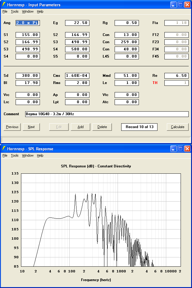
It is even flatter with an added 2.2mH inductor.
Following advise here, I "measured" the T&S parameters of one of my 10G40 and it models as follows in the same tapped horn (quite similar).
I am putting measured in quotes because:
- I used SpeakerWorkshop measure in free air method
- I did not do the added mass or closed box bit, so do not have Vas
- my speaker stand was not necessarily as rigid as it should be.
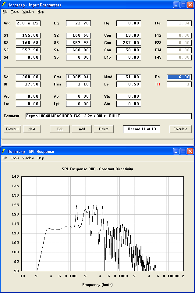
Again, it is a bit better with an added inductor.
I then started the build...
Here is how it looks before closing the box.
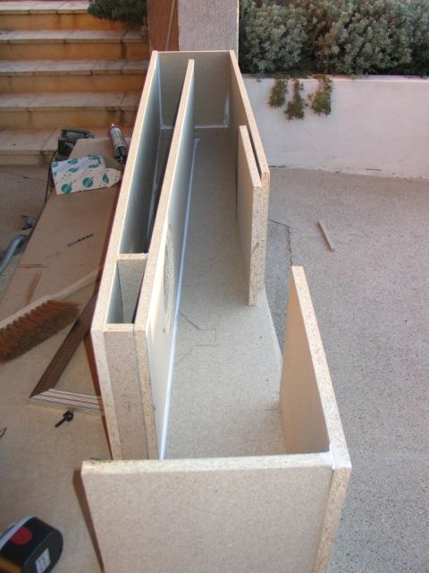
Where the driver will go...
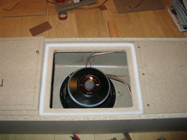
The driver in place ready to be sealed...
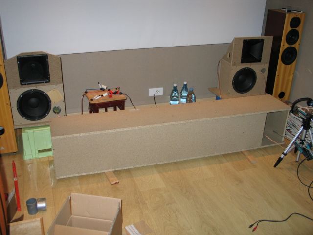
The thing in place for measurement (mic in the mouth)...
Up to this point, I was a happy man...
With the pieces cut to dimension (as we can get from our Home Depot equivalents here in France) it took me 4 hours prompt to fully assemble the thing.
[tbc]
You need to make the hole opening into the throat the full size of the cone. The S2 area only concerns the horn, make the woofer hole as big as the cone. Your picture labeled "Where the driver will go..." shows me yor problem. I made the same mistake on my very first tapped horn. Do not feel bad, it looks like you have a big enough access panel to cut the woofer opening larger.
Rgs, JLH
I messed up with to many open windows to copy from!
Thanks Sabbelbacke your correction was well presented!
I posted the source in error .
Your comments are completly correct for the nearfield response from a horn to.
I have made a small PDF directly from D'Appolito's Testing Loudspeakers. It's a bit big to post on the forum. So here it is!
My apologies!
http://www.filefactory.com/file/af6e70e/n/Groundplane_Measurements_PDF
I'm still looking for the paper on low frequency horn measurement. Never have the right stuff at hand when you need it!
Mark
Re: I messed up with to many open windows to copy from!
Hy Mark,
I was wondering if one could lookup the book in google-books? Its restricted in germany, how about in the US oder canada?
I hope after I switch to MAC on my desktop the "search" will help me out on situations like this. Similar mechanisms on windows didn´t appeal to me, fed up too much ressources.
Hy Mark,
Thanx. that´s very helpful as a basic starting point. Looks familiarI have made a small PDF directly from D'Appolito's Testing Loudspeakers. It's a bit big to post on the forum. So here it is!
I was wondering if one could lookup the book in google-books? Its restricted in germany, how about in the US oder canada?Oh yes, I know the situationI'm still looking for the paper on low frequency horn measurement. Never have the right stuff at hand when you need it!
I hope after I switch to MAC on my desktop the "search" will help me out on situations like this. Similar mechanisms on windows didn´t appeal to me, fed up too much ressources.Not available on Google Books
But it is available beside me!!!
Sometimes we have to break down and actually buy these crazy things!
I'll be damned if I can find the paper that tells exactly how to measure a horn low end. The papers on Keele's site give hints. I just read a couple or three of the papers and there are enough tid bits to point you in the right direction.
A hunting I will go!
Mark
Yes, this book definitely is one of the "must haves"... BTW, if some german reader reads this, I happen to have three of them (one english, one german and one german as a spare), one I´d sell, its only collecting dust
Good luck on your search, looking forward to the results.
Good luck on your search, looking forward to the results.
Hi,
JLH and jm_kzo:
I too noticed the throat chamber with the reduced opening into the horn proper, but when I modelled it in Hornresp it didn't seem to make a difference. It would be helpful if JLH could expand a little on his practical experience with this area. Usually these tapped horn models seem to be quite touchy in the throat area. As to the difference between jm_kzo's model and measurement: 1. check all dimensions, 2. I would guess that air leaks, especially around the driver area will do a tapped horn in, 3. Go with Sabbelbacke's advice and get "Testing Loudspeakers_Joseph-D'Appolito".
carpenter:
Thanks for the picture, looks interesting. Where do you find the time?
fb:
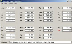
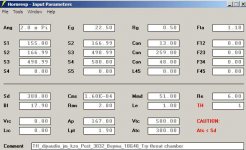
Just playing with the TD10H in Hornresp it looks like any number of reasonable alignments can be found with an acceptable (to me about +- 3dB) amount of ripple. This particular driver seems to respond well to a series inductor (Le add 7mH, Re add 0.35Ohm). And, if the enclosure width is a problem, the use of multiple drivers seems to be the way to go. I'll attach the Hornresp input screen for a dual with a similar volume to your design, just something to get you started.
High compression ratios are reported to destroy woofers, particularly if they are used for high-level output over longer periods of time, e.g.: PA, instrument use. If you are looking for output in excess of 120dB from 35Hz to 90Hz that may qualify.
Regards
JLH and jm_kzo:
I too noticed the throat chamber with the reduced opening into the horn proper, but when I modelled it in Hornresp it didn't seem to make a difference. It would be helpful if JLH could expand a little on his practical experience with this area. Usually these tapped horn models seem to be quite touchy in the throat area. As to the difference between jm_kzo's model and measurement: 1. check all dimensions, 2. I would guess that air leaks, especially around the driver area will do a tapped horn in, 3. Go with Sabbelbacke's advice and get "Testing Loudspeakers_Joseph-D'Appolito".
carpenter:
Thanks for the picture, looks interesting. Where do you find the time?
fb:
Just playing with the TD10H in Hornresp it looks like any number of reasonable alignments can be found with an acceptable (to me about +- 3dB) amount of ripple. This particular driver seems to respond well to a series inductor (Le add 7mH, Re add 0.35Ohm). And, if the enclosure width is a problem, the use of multiple drivers seems to be the way to go. I'll attach the Hornresp input screen for a dual with a similar volume to your design, just something to get you started.
High compression ratios are reported to destroy woofers, particularly if they are used for high-level output over longer periods of time, e.g.: PA, instrument use. If you are looking for output in excess of 120dB from 35Hz to 90Hz that may qualify.
Regards
Attachments
tb46 said:
carpenter:
Thanks for the picture, looks interesting. Where do you find the time?
Thanks for that. The economy has me working part time. So, when I'm not working on my house, or someone else's, I fabricate amplifiers and speakers.
Re: jm_kzo's Beyma 10G40 TH
Ok, first off, if I understand correctly, you measured the driver parameters but did NOT add weight and get a vas measurement, then you input the values you measured and mixed in the manufacturer's value for vas. If so, this is not an accurate measurement, since cms, rms, bl, mmd are all derived using vas as a starting point. *(I'm new to this myself so I may be wrong but I don't think so). So IMO your driver parameter inputs are not correct and that's a shaky ground for a foundation. At this point there's nothing you can do about that unless you want to go back and get complete measurements. If vas is wrong, almost all the other parameters are going to be wrong too.
Breaking in the driver will change the parameters, no doubt about that. But you are supposed to break in the driver first and then measure it. The breaking in process does not require hundreds of hours for these purposes. Feeding the naked driver (no box or baffle) low hz sine waves with enough power to get near xmax for a few minutes (or an hour if you like) should be plenty of breaking in to achieve accurate measurements.
Pinhole leaks will ruin your design. And that's all there really is to say on that subject. But I'll say it again anyway. Pinhole leaks will ruin your design.
I have no idea what effect the constricted driver plate has, so I'd pay attention to JLH on this one and either research the issue or just open the hole up the size of the driver cone.
jm_kzo said:
The manufacturer spec states a Vas of 33 liters, do you think it could be too high ?
What about breaking in the driver ?
These PA things do havee stiff suspensions and everybody says that they still evolve after tens of hours if not hundreds...
With regards to pinhole leaks, they are definitely a few of them...
Ok, first off, if I understand correctly, you measured the driver parameters but did NOT add weight and get a vas measurement, then you input the values you measured and mixed in the manufacturer's value for vas. If so, this is not an accurate measurement, since cms, rms, bl, mmd are all derived using vas as a starting point. *(I'm new to this myself so I may be wrong but I don't think so). So IMO your driver parameter inputs are not correct and that's a shaky ground for a foundation. At this point there's nothing you can do about that unless you want to go back and get complete measurements. If vas is wrong, almost all the other parameters are going to be wrong too.
Breaking in the driver will change the parameters, no doubt about that. But you are supposed to break in the driver first and then measure it. The breaking in process does not require hundreds of hours for these purposes. Feeding the naked driver (no box or baffle) low hz sine waves with enough power to get near xmax for a few minutes (or an hour if you like) should be plenty of breaking in to achieve accurate measurements.
Pinhole leaks will ruin your design. And that's all there really is to say on that subject. But I'll say it again anyway. Pinhole leaks will ruin your design.
I have no idea what effect the constricted driver plate has, so I'd pay attention to JLH on this one and either research the issue or just open the hole up the size of the driver cone.
I too noticed the throat chamber with the reduced opening into the horn proper, but when I modelled it in Hornresp it didn't seem to make a difference.
I don't think hornresp can calculate a restricted opening entering into S2, so I'm not sure how you did this. Anyway, I'm usually wrong when it comes to hornresp, so...
Post #3054
Hi carpenter,
Sorry about the employment situation, the economy has even started to cut into the oil field jobs in this area (Permian Basin). Some of the lower skill jobs were being ramped down quickly as the oil price went down. On the other hand skilled people are still doing fine. I'm willing to bet that the oil price will not stay this low for any length of time, and then we're back to looking for helping hands, and not finding any. Our big depression occured in the late 1980's when we lost about 350,000 jobs in the oil and gas industry.
Anyway, you seem to have found an excellent use for your extra time.
Regards,
Re: Post #3054
Yep...
Early 80s caught me off guard too. Everything cycles.
tb46 said:Hi carpenter,
...Anyway, you seem to have found an excellent use for your extra time.
Regards,
Yep...
Early 80s caught me off guard too. Everything cycles.
just a guy said:I don't think hornresp can calculate a restricted opening entering into S2, so I'm not sure how you did this. Anyway, I'm usually wrong when it comes to hornresp, so...
I think you can do this with the front chamber function in hornresp. Quite convenient in the TH wizard. Also, it should have nearly no influence to make the opening smaller, as the length of the opening is very small. Think of the unity horn design with its little holes. It has only influence on the high frequencies.
About the malfunctioning TH: You can find harmfull leaks easily if you play some loud deep sine tone and then move your hand around every spot that could have a leak. You will notice the air blowing out of the hole. Check especially in the vicinity of the driver.
- Home
- Loudspeakers
- Subwoofers
- Collaborative Tapped horn project